Structure and detection method of a fiber point diffraction interferometer

A point-diffraction interferometer and optical fiber technology, which is applied in the field of optical surface shape detection, can solve the problems of the overall structure being limited by space, inconvenient adjustment and operation, and unsatisfactory spherical waves, and achieve low cost, easy manufacture, and easy space. Effect

Inactive Publication Date: 2011-12-21
DALIAN NATIONALITIES UNIVERSITY
View PDF5 Cites 23 Cited by
  • Summary
  • Abstract
  • Description
  • Claims
  • Application Information

AI Technical Summary

Problems solved by technology

[0006] 1. Since it is difficult to make an ideal circular mask hole by etching and other methods, the light wave diffracted by the hole may cause the spherical wave to be less than ideal
[0007] 2. The spherical wave generated by a small hole in a mask plate itself has little energy because the small hole is too small, and it must be divided into two parts: the reference wave surface and the measurement wave surface. When detecting a circular surface, it

Method used


Image

  • Structure and detection method of a fiber point diffraction interferometer
  • Structure and detection method of a fiber point diffraction interferometer
  • Structure and detection method of a fiber point diffraction interferometer

Examples


Embodiment Construction

[0036] The present invention will be further described below in conjunction with the accompanying drawings.

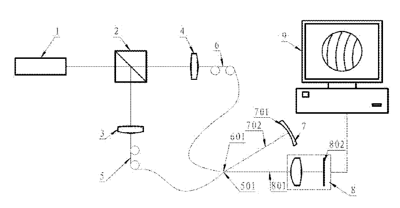
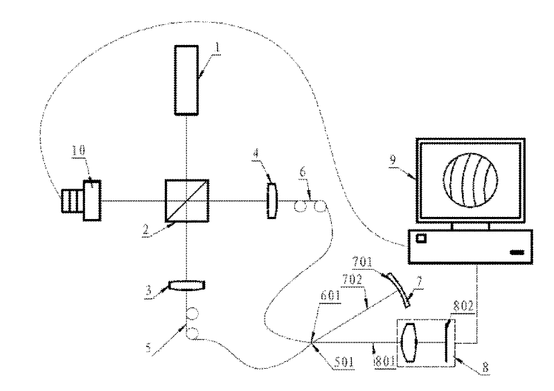
[0037] Such as figure 1 As shown, the point diffraction interferometer of the present invention at least includes: laser 1, beam splitter 2, measuring optical coupling lens 3, reference optical coupling lens 4, measuring optical fiber 5, reference optical fiber 6, measured element 7 and its adjustment mechanism, charge A device imaging system 8 and an image analysis computer 9 are coupled.

[0038] The laser light generated by the laser 1 is divided into two beams of light by the beam splitter 2, one beam of light is used as the measurement light, coupled to the measurement optical fiber 5 by the measurement optical coupling lens 3, and the other beam is used as the reference light, coupled by the reference optical coupling lens 4 into reference fiber 6.

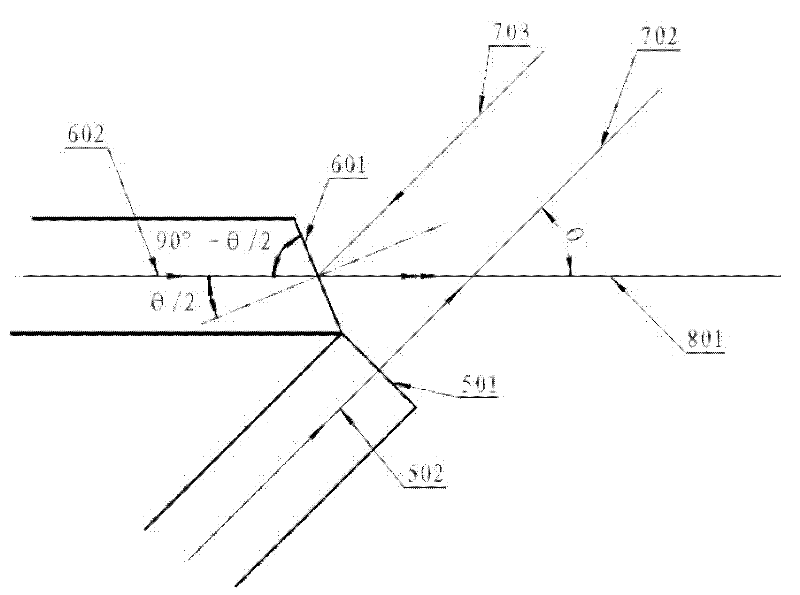
[0039] The standard spherical wave emitted from the outgoing end face 601 of the reference fiber is used as a re...


PUM


Abstract

The invention discloses a structure of an optical fiber point diffraction interferometer and a detection method thereof. The structure at least includes a laser, a beam splitter, a measuring optical coupling lens, a reference optical coupling lens, a measuring optical fiber, a reference optical fiber, a measured element and its Adjustment mechanism, charge-coupled device imaging system and image analysis computer; the light emitted by the laser is incident on the beam splitter, and the light is divided into two beams, one beam is coupled to the measurement optical fiber through the measurement optical coupling lens, and the other beam is coupled to the measurement fiber through the measurement optical coupling lens. The reference optical coupling lens is coupled to the reference optical fiber, the two beams of light overlap and interfere, and interference fringes are generated on the imaging surface of the charge-coupled device imaging system, and the image analysis computer is used to analyze the interference fringes to obtain the surface shape of the measured surface of the measured component situation. The invention utilizes two optical fiber cores to diffract to generate standard circular spherical waves as ideal spherical wave light sources, which are respectively used as reference spherical waves and measurement spherical waves. The optical fiber of the invention is easy to manufacture and has low cost.

Description

technical field [0001] The invention relates to a technology and device for optical surface shape detection, especially point diffraction interference technology and interferometer using optical fiber to generate standard spherical waves, which are used in the fields of high-precision optical element surface shape detection and optical system wave front detection. Background technique [0002] With the continuous development of optical technology and technology, the precision requirements for optical components are getting higher and higher, and even the optical diffraction limit resolution is required. The processing accuracy of optical components is mainly limited by the accuracy of the interference standard mirror itself in interferometric technology. The interference standard mirror of the high-precision interferometer is difficult to process and assemble, and the cost is very high. The technique of generating standard spherical waves using point diffraction (US Patent ...

Claims


Application Information

Patent Timeline
IPC IPC(8): G01B9/02G01B11/24
Inventor 曹晓君张学军
Owner DALIAN NATIONALITIES UNIVERSITY
Why Eureka
Try Eureka