Electrical connector assembly with direct connection terminals

A technology for electrical connectors and electrical connections, which is applied to parts of connection devices, printed circuit components, and electrical connection printed components, etc., and can solve problems such as signal attenuation and large contacts

Inactive Publication Date: 2011-12-21
TE CONNECTIVITY CORP
View PDF5 Cites 33 Cited by
  • Summary
  • Abstract
  • Description
  • Claims
  • Application Information

AI Technical Summary

Problems solved by technology

To overcome such problems, the contacts have to be made larger, which causes additional signal attenuation problems
Additionally, such systems employ relatively short contacts, which can limit these systems to relatively thin circuit boards, or limit connections to upper layers of the circuit board

Method used


Image

  • Electrical connector assembly with direct connection terminals
  • Electrical connector assembly with direct connection terminals
  • Electrical connector assembly with direct connection terminals

Examples


Embodiment Construction

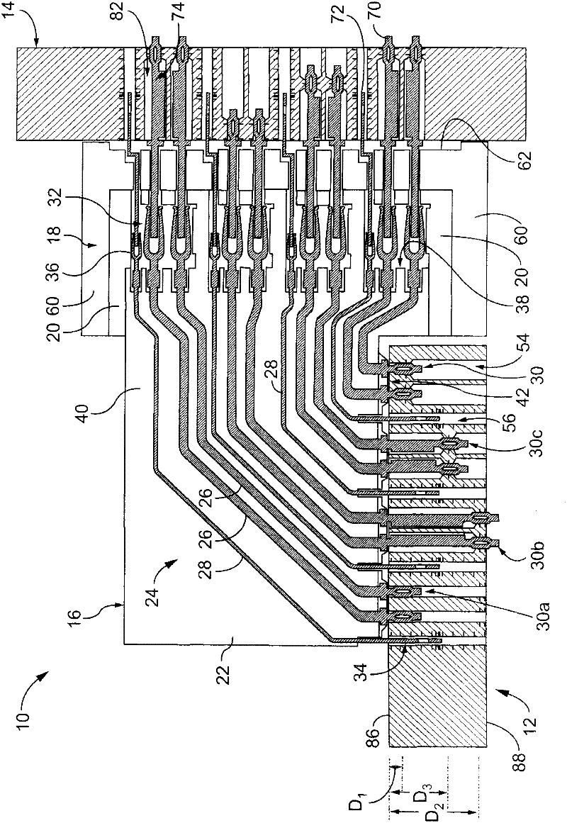
[0012] figure 1 is a cross-sectional view of an exemplary embodiment of the electrical connector assembly 10 . The connector assembly 10 includes a pair of circuit boards 12 and 14 , a receptacle connector 16 , and a plug connector 18 . The receptacle connector 16 is mounted on the circuit board 12 and the plug connector 18 is mounted on the circuit board 14 . The socket connector 16 and plug connector 18 are connected together to electrically connect the circuit boards 12 and 14 . exist figure 1 In the exemplary embodiment of the present invention, the receptacle connector 16 and the plug connector 18 are oriented such that the connectors 16 and 18 form an approximately right angle connection between the circuit boards 12 and 14 . Alternatively, receptacle connector 16 and header connector 18 may be oriented such that circuit boards 12 and 14 may be arranged at any other angle relative to each other, such as but not limited to approximately parallel.

[0013] The receptac...


PUM


Abstract

An electrical connector assembly (10) includes a circuit board (12) having a through hole (54) extending at least partially therethrough along a through hole axis (106). The circuit board has traces (104) and mounting pads (102) electrically connected to the traces. The mounting pad is exposed in the through hole. An electrical connector (16) is mounted on the circuit board. The electrical connector includes a housing (20) and signal terminals (26) held by the housing. The signal terminal has a mounting contact (30) arranged to be received in each of said through holes. Each via has a stepped diameter along the via axis with a constricted region (94) adjacent the mounting pad, and the mounting contact engages the mounting pad within the constricted region of the via.

Description

technical field [0001] The present invention relates to an electrical connector assembly comprising an electrical connector mounted on a circuit board. Background technique [0002] In order to meet the demands of digital multimedia, it is generally desired that existing digital communication devices have higher data processing capabilities. Accordingly, electrical connectors used to interconnect circuit boards must handle ever increasing signal speeds at ever increasing signal densities. One application in which such electrical connectors are used is in high speed, differential electrical connectors, such as those commonly encountered in telecommunications or computing applications. In the conventional approach, two circuit boards are interconnected to each other in a backplane and daughterboard configuration. However, at the solder pins of the circuit board to which the electrical connector is connected, it is difficult to increase density while maintaining electrical pe...

Claims


Application Information

Patent Timeline
Patent Type & Authority Applications(China)
IPC IPC(8): H01R12/58H05K1/11
CPCH01R12/585H05K1/115H05K2201/10189H05K3/366H01R13/514H05K3/308H01R12/52H01R12/724H05K2201/09845H01R13/6473H05K2201/044
Inventor 查德·W·摩根
Owner TE CONNECTIVITY CORP
Why Eureka
Try Eureka