led lens

A technology of LED lens and axial direction, which is applied in the direction of point light source, lighting and heating equipment, parts of lighting device, etc., which can solve the problems of inconvenience

Active Publication Date: 2011-12-28
LITE ON ELECTRONICS (GUANGZHOU) LTD +1
View PDF4 Cites 7 Cited by
  • Summary
  • Abstract
  • Description
  • Claims
  • Application Information

AI Technical Summary

Problems solved by technology

[0004] This shows that above-mentioned existing traditional light bulb obviously still ha

Method used


Image

  • led lens
  • led lens
  • led lens

Examples


Embodiment Construction

[0028] In order to further explain the technical means and effects of the present invention to achieve the intended purpose of the invention, the specific implementation, structure, characteristics and effects of the LED lens proposed according to the present invention will be described in detail below in conjunction with the accompanying drawings and preferred embodiments. The description is as follows.

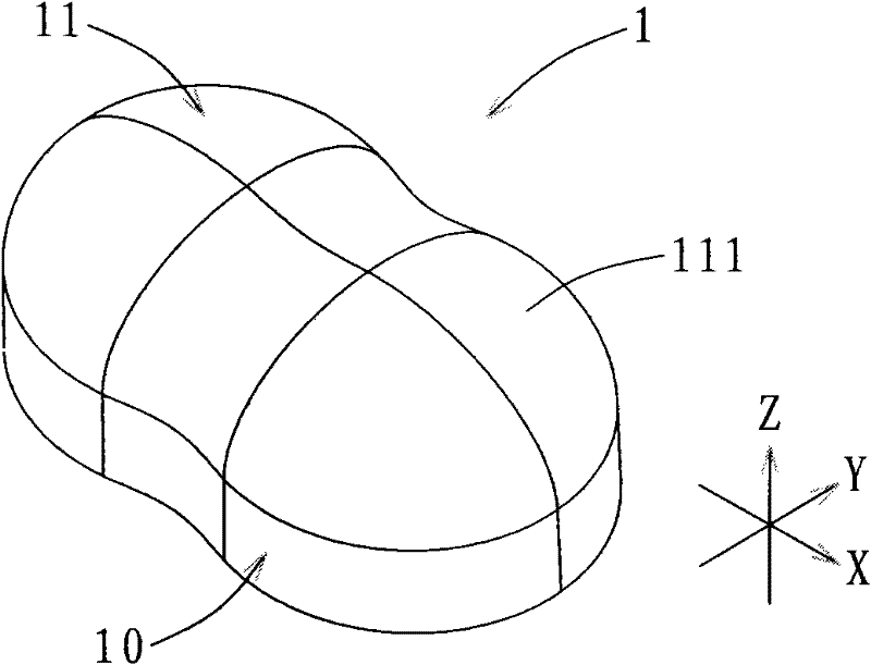
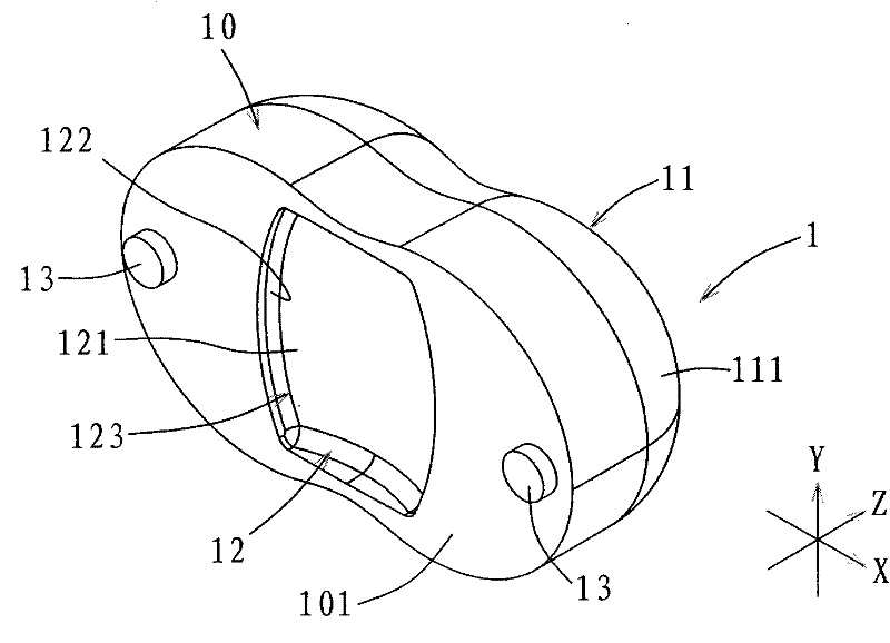
[0029] refer to figure 1 and figure 2 As shown, a preferred embodiment of the LED lens of the present invention is made of plastic material integrally formed (such as injection molding). At least one positioning protrusion 13 .

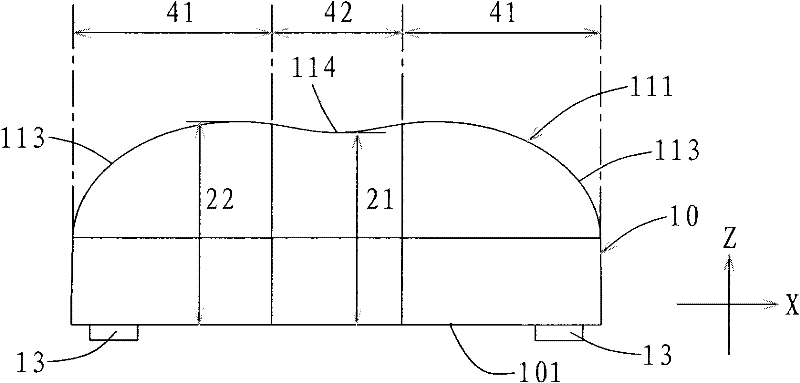
[0030] It should be explained in advance that the first axis referred to below is the X axis, the second axis referred to is the Y axis, and the third axis is the Z axis. The X axis and the Y axis define a plane perpendicular to each other, and the Z axis The axis direction is perpendicular to the plane defined by the X-axis and the Y-axis.

[...


PUM


Abstract

The invention relates to an LED (light emitting diode) lens used for covering an LED luminous source. The LED lens comprises a body, a bright dipping part and an incoming light concave part, wherein the body is made of a nonopaque material; the bright dipping part is formed on the body and provided with a bright dipping surface with a free curved surface, and the bright dipping surface is dividedinto two regions with an outward convex arced surface and a region with an inward concave arc surface in a first axial direction, and the region with the inward concave arc surface is connected between the two regions with the outward convex arc shape surface; the minimum width of the region with the inward concave arc surface in a second axial direction and a third shaft direction is less than the maximum width of the two regions with the outward convex arc shape surface in the second shaft and the third shaft direction; and the incoming light concave part is of a concave structure which is formed at one side face, opposite to the bright dipping part, of the body so as to accommodate the LED luminous source, and the incoming light concave part is provided with an incoming light surface of which two regions at two sides in a first axial direction extend downwards in an opposite and slant mode.

Description

technical field [0001] The invention relates to a lens, in particular to an LED lens. Background technique [0002] Due to the advantages of high luminous efficiency, long life, and low power consumption, light-emitting diodes have gradually replaced traditional light bulbs in recent years and become the first choice for a new generation of light-emitting components. Street lamps, which are in great demand, are gradually replacing traditional light bulbs with light-emitting diodes. [0003] Generally, when street lamps are illuminated, the lighting area needs to cover the entire width of the road. Therefore, the better lighting area of ​​the street lamp should be rectangular so as to cover the entire width of the road. [0004] This shows that above-mentioned existing traditional light bulb obviously still has inconvenience and defect in structure and use, and urgently needs to be further improved. Therefore, how to create a LED lens with a new structure is one of the curr...

Claims


Application Information

Patent Timeline
IPC IPC(8): F21V5/04F21Y101/02
CPCF21V5/04F21Y2101/02F21W2131/103F21Y2115/10
Inventor 李仲恩
Owner LITE ON ELECTRONICS (GUANGZHOU) LTD
Why Eureka
Try Eureka