
Visible light audio transmission system based on phase-locked loop

A transmission system and phase-locked loop technology, applied in the field of visible light audio transmission system, can solve the problems of unreliability, poor anti-interference, high system operation and maintenance costs, avoid information leakage, increase flexibility, and improve anti-interference sexual effect

Inactive Publication Date: 2016-07-06
HANGZHOU DIANZI UNIV
View PDF14 Cites 8 Cited by
  • Summary
  • Abstract
  • Description
  • Claims
  • Application Information

AI Technical Summary

Problems solved by technology

In addition to the power cord, traditional wired devices also need to be connected to a dedicated audio signal line, which is inflexible and inconvenient
However, wireless devices based on WIFI, radio frequency or Bluetooth require specific devices or occasions to be used, and the confidentiality is not good, and they are easily interfered by the outside world, which greatly limits the wide application of these wireless devices, causing them not to work well get promoted
[0004] The visible light audio transmission systems that have appeared in recent years mostly use complex modulation and demodulation methods, which makes the operation and maintenance costs of the system very high
Although some systems are simple to implement, they have poor anti-interference and are unreliable

Method used


Image

  • Visible light audio transmission system based on phase-locked loop
  • Visible light audio transmission system based on phase-locked loop
  • Visible light audio transmission system based on phase-locked loop

Examples


Embodiment Construction

[0025] The present invention will be described in detail below in conjunction with the accompanying drawings.

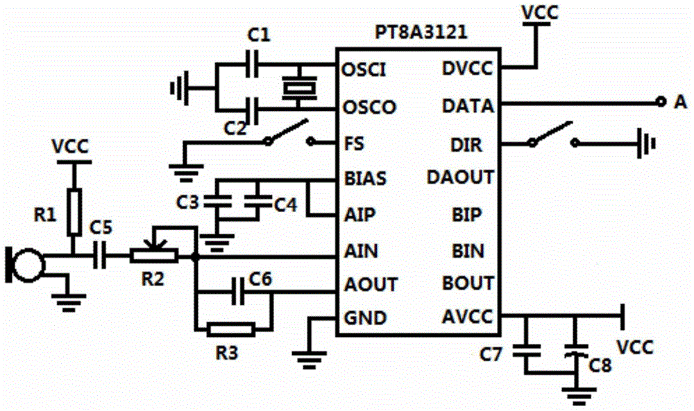
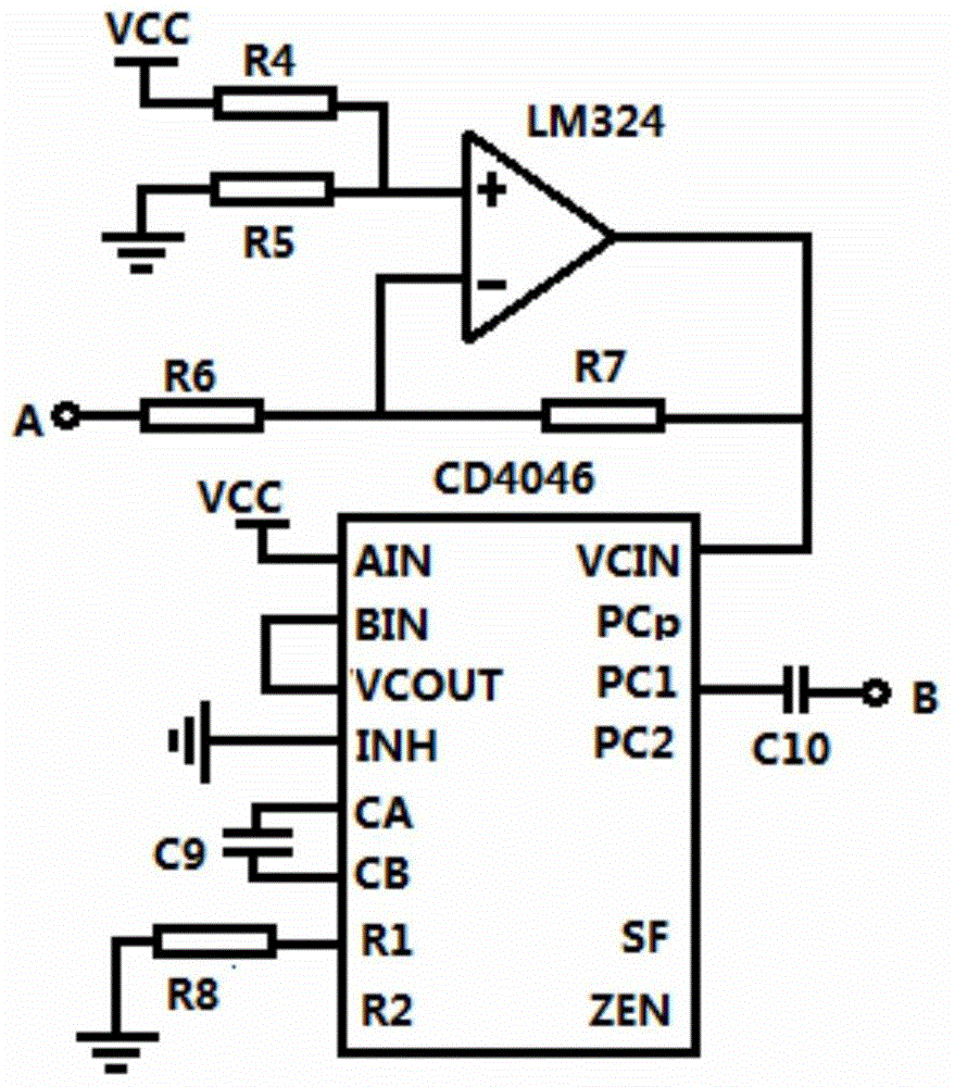
[0026] refer to figure 1 , a visible light audio transmission system based on a phase-locked loop, including a microphone MIC of the transmitting part, an analog-to-digital conversion module 1, a modulation module 2, and a transmitting circuit module 3, a receiving circuit module 4 of the receiving part, a demodulation module 5, and a waveform shaping module 6 and digital-to-analog conversion module 7. In the transmitting part, the external sound is received by the microphone MIC, which is input to the analog-to-digital conversion module 1 to convert the analog quantity into a digital quantity, and then the digital quantity is modulated by the modulation module 2, and then the modulated signal is loaded onto the LED light by means of the transmitting circuit module 3 and emitted. The receiving part receives the modulated optical signal by the silicon photocell, and ...


PUM


Abstract

The invention discloses a visible light audio transmission system based on a phase-locked loop. The existing visible light audio transmission system has high running cost and maintenance cost and poor anti-interference performance. A microphone receives the outside sound, the sound is input into an analog-to-digital conversion module to convert the analog quantity to the digital quantity, and then after a modulation module modulates the digital quantity, a modulated signal is loaded to LED (Light Emitting Diode) light to be transmitted through a transmitting circuit module; a silicon photocell receives a modulated light signal and converts the modulated light signal to an electric signal through a receiving circuit module, a demodulation module demodulates the electric signals and then inputs the electric signal to a waveform shaping module, the digital quantity of the transmitting part is restored, the signal is converted to an analog audio signal through a digital-to-analog conversion module, and lastly, the analog audio signal is amplified through a power amplifier and drives a loudspeaker; and the modulation module and the demodulation module both adopt CD4046 phase-locked loops. According to the system, frequency modulation and demodulation is carried out conveniently and easily by employing the CD4046 phase-locked loops, and signal transmission is performed by employing the LED light, so that the confidentiality is good.

Description

technical field [0001] The present invention relates to a visible light audio transmission system, in particular to a visible light audio transmission system using a phase-locked loop to modulate and demodulate digital signals. Background technique [0002] LED is called the fourth-generation lighting source or green light source. It has many advantages such as energy saving, environmental protection, small size, and long life, and has a wide application prospect. With the continuous advancement of LED technology, it is considered that it will eventually replace existing lighting equipment, and due to its high-speed modulability, visible light communication technology based on it has also been well developed. [0003] There are many audio transmission methods, and existing audio playback devices such as speakers or earphones are mainly divided into two categories: wired and wireless. In addition to the power cord, traditional wired devices also need to be connected to a ded...

Claims


Application Information

Patent Timeline
IPC IPC(8): H04B10/116G10L19/16
CPCH04B10/116G10L19/16
Inventor 张钰卫振奇胡万鹏
Owner HANGZHOU DIANZI UNIV
Learn More