
Elevation-depression angle regulating mechanism for fan

An angle adjustment, fan technology, applied in mechanical equipment, machine/engine, pump control, etc., can solve the problems of positioning hole positioning failure, difficult to achieve appearance, connection shape restrictions, etc., to achieve reliable life, large positioning range, positioning angle Adjustable range of effects

Inactive Publication Date: 2012-01-11
MIDEA GRP CO LTD
View PDF7 Cites 2 Cited by
  • Summary
  • Abstract
  • Description
  • Claims
  • Application Information

AI Technical Summary

Problems solved by technology

[0003] First, the angle positioning is positioned by the positioning hole on the metal clip, the angle adjustment is small and cannot be adjusted steplessly;
[0004] Second, it is difficult to assemble components such as torsion springs and positioning beads in workshops;
[0005] Third, due to the small friction area, after long-term pitching operation, the groove mark on the easy-to-wear part of the positioning hole on the metal sheet will cause positioning failure;
[0006] Fourth, this mechanism leads to more restrictions on the shape of the connection between the nose and the fuselage, and many appearances are difficult to achieve

Method used


Image

  • Elevation-depression angle regulating mechanism for fan
  • Elevation-depression angle regulating mechanism for fan
  • Elevation-depression angle regulating mechanism for fan

Examples


Embodiment Construction

[0020] The present invention will be further described below in conjunction with the accompanying drawings and specific embodiments.

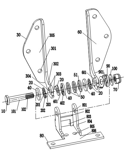
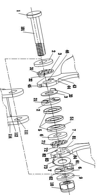
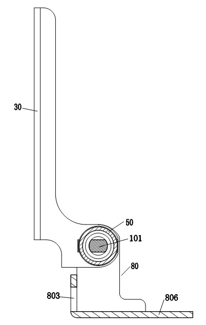
[0021] Such as Figures 1 to 4 As shown, it is a fan pitch angle adjustment mechanism, the present invention is characterized in that it includes a pivot 1 with a waist-shaped shaft 101, a left movable bracket 4, a right movable bracket 8, a first group of friction plates 2, a first group of Oil-gathering friction plates 3, a group of elastic gaskets 5, a second group of oil-gathering friction plates 7, a second group of friction plates 6, flat gaskets 9, end seals 10 and fixing brackets 11; on the fixing brackets 11 There are two supporting parts 114, and the two supporting parts 114 are radially positioned relative to the waist-shaped shaft 101, that is, the two supporting parts 114 cannot rotate relative to the waist-shaped shaft 101; the first group of oil-gathering friction plates 3 includes a 4 two pieces of oil-gathering friction pla...


PUM


Abstract

The invention relates to an elevation-depression angle regulating mechanism for a fan. The elevation-depression angle regulating mechanism is characterized by comprising a pivot, a left movable support, a right movable support, a first group of friction plates, a second group of friction plates, a first group of poly-oil friction plates, a second group of poly-oil friction plates, a set of elastic shims, a flat gasket, an end sealing piece and a fixed support, wherein the pivot is provided with a waist-form shaft lever; the fixed support is provided with two supporting parts and the two supporting parts are positioned along radial direction relative to the waist-form shaft lever; one friction plate of the second group of friction plates is provided with a positioning bulge; the right movable support is provided with a track groove; the positioning bulge is positioned in the track groove and can slide; the waist-form shaft lever is fixed by the end sealing piece after successively passing through one supporting part, the first group of friction plates, the first group of poly-oil friction plates, the left movable support, a set of elastic shims, the second group of friction plates, the second group of poly-oil friction plates, the right movable support, the other supporting part and the flat gasket; the first group of friction plates and the second group of friction plates can not radially rotate relative to the waist-form shaft lever; the left movable support and the right movable support can radially rotate relative to the waist-form shaft lever; and the regulating mechanism provided by the invention has the advantages that a positioning range of mechanism angle is large, a positioning angle range is adjustable, security and reliable stepless angle positioning can be realized, no noise exists and hand feeling is good during the elevation-depression operation, structure is simple, assembly is convenient and service life is reliable.

Description

technical field [0001] The invention belongs to the technical field of a table fan, a table fan or a floor fan, and in particular relates to a fan pitch angle adjustment mechanism for a table fan, a table fan, or a floor fan. Background technique [0002] Most of the current pitch angle adjustment mechanisms of table fans, platform fans or floor fans are composed of connectors, metal clips, positioning beads, positioning nail springs, torsion springs, bolts, and nuts. , There are positioning holes on the metal clip. This structure has the following disadvantages: [0003] First, the angle positioning is positioned by the positioning hole on the metal clip, the angle adjustment is small and cannot be adjusted steplessly; [0004] Second, it is difficult to assemble components such as torsion springs and positioning beads in workshops; [0005] Third, due to the small friction area, after long-term pitching operation, the groove mark on the easy-to-wear part of the positio...

Claims


Application Information

Patent Timeline
Patent Type & Authority Applications(China)
IPC IPC(8): F04D27/00
Inventor 邓建辉刘维亮陈宝君王伟光
Owner MIDEA GRP CO LTD
Learn More