Eureka AIR delivers breakthrough ideas for toughest innovation challenges, trusted by R&D personnel around the world.

Air suction type safety valve

A safety valve and air extraction technology, which is applied in the field of safety valves, can solve problems such as slow seat return, valve opening height, discharge time and speed that cannot be adjusted on site, and flow that cannot be adjusted and controlled.

Active Publication Date: 2012-01-11
YONGYI VALVE
View PDF5 Cites 6 Cited by
  • Summary
  • Abstract
  • Description
  • Claims
  • Application Information

AI Technical Summary

Problems solved by technology

[0003] The main defect of the above structure is: the spring direct load safety valve is directly ensured by the spring force to overcome the medium force under the disc to ensure the seal. When it is under the working pressure of the system, the sealing specific pressure at the sealing surface is small, easy to leak, and the opening height is Limited by the method of mechanical blocking, the opening height, discharge time and speed of the valve cannot be adjusted on site
The piston cavity of the main valve of the pilot safety valve needs to be sealed with a good sealing O-ring or other sealing rubber, which has poor temperature resistance, and the opening height, discharge time and speed of the valve cannot be adjusted on site
The lever type safety valve cannot adjust and control the flow on the inlet side when it is discharged, and the seat return is slow, and the opening and closing pressure difference is large

Method used


Image

  • Air suction type safety valve
  • Air suction type safety valve
  • Air suction type safety valve

Examples


Embodiment Construction

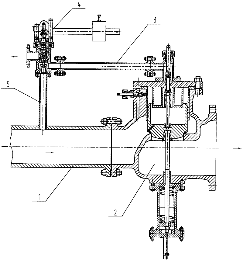
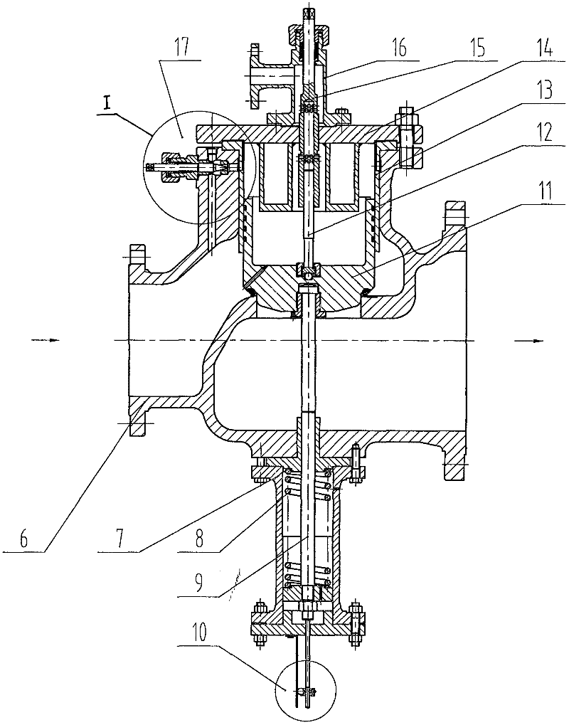
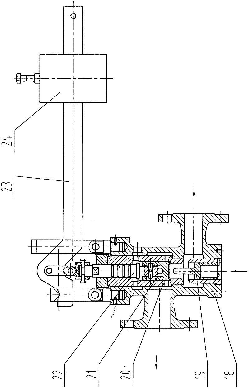
[0015] Such as figure 1 The suction type safety valve shown includes a main valve 2 and a pilot valve 4. The main valve 2 includes a valve body 6, a disc 11, a valve cover 14, and a valve stem. The valve stem is composed of an upper valve stem 12 and a lower valve stem 9. , the lower end of the upper valve rod 12 is fixed on the center of the upper plane of the valve disc 11 . There is an upwardly extending cylinder on the outer edge of the upper end surface of the valve disc 11. A piston cavity is formed between the cylinder and the valve cavity on the inlet side of the valve body 6 and the valve cover 14. The valve disc 11 is connected to the inlet channel of the valve body 6 and the piston cavity. small hole. The valve body 6 is formed with a through hole communicating with the inlet passage and the piston cavity, and a flow regulator 17 is arranged on the through hole. A height adjustment screw sleeve 15 is installed between the valve cover 14 and the piston chamber, and...


PUM


Abstract

The invention relates to an air suction type safety valve, which comprises a main valve and a pilot valve. Primarily, a piston chamber is formed between a valve flap of the main valve and a valve cavity as well as a valve cover on the side of a valve body inlet; the valve flap is provided with a small hole for communicating a valve body inlet passage with the piston chamber; the valve body is provided with a through hole for communicating the inlet passage thereof with the piston chamber; a flow adjuster is arranged on the through hole; an opening height adjusting thread sleeve is arranged between the valve cover and the piston chamber; a seal chamber which is communicated with a transverse inlet of the pilot valve is formed between the opening height adjusting thread sleeve and the valvecover; the center of the opening height adjusting thread sleeve is provided with an inner hole for communicating the piston chamber with the seal chamber; and opening height of the valve flap and main valve flow coefficient are adjusted by adjusting relative position of the opening height adjusting thread sleeve and an upper valve rod; and closing speed of the main valve and the opening and closing pressure difference are controlled by adjusting an adjusting needle of the flow adjuster. The valve has the advantages that the opening height, discharge coefficient, discharge time and opening andclosing pressure difference can be adjusted and the opening height can be observed at any time and the like, and the safety valve is suitable to be used for various medium pipelines and vessels.

Description

technical field [0001] The invention relates to the field of valves, in particular to a safety valve. Background technique [0002] At present, the structural types of safety valves mainly include spring direct load safety valves, pilot safety valves and lever safety valves. The spring direct load type safety valve directly overcomes the force of the medium under the disc by the force of the spring, and generates a certain sealing specific pressure on the seal of the disc to achieve the effect of sealing. When the pressure on the inlet side rises to a certain pressure value When the force of the medium overcomes the spring force, the valve disc is pushed up to discharge. When the pressure on the inlet side drops to a certain value, the valve disc is closed under the action of the spring force. The pilot safety valve is composed of a main valve and a pilot valve. The pilot valve is a separate spring-loaded safety valve. When the system pressure rises to the preset set pressu...

Claims


Application Information

Patent Timeline
Patent Type & Authority Applications(China)
IPC IPC(8): F16K17/10F16K17/164F16K37/00
Inventor 赵春岳郑子林
Owner YONGYI VALVE
Why Eureka
Eureka Blog
Learn More