Drives for hinges and pivoting adjustment arms

A technology that rotates around an axis and drives a device. It is applied to hinges with pins, switches with brakes, and door/window accessories. question

Active Publication Date: 2015-12-16
伍志勇
View PDF6 Cites 0 Cited by
  • Summary
  • Abstract
  • Description
  • Claims
  • Application Information

AI Technical Summary

Problems solved by technology

It is said that the invention sets more than two stages of springs in the hinge, so that when the hinge is opened or closed to a certain angle, the hinge can be fully opened or closed automatically through the resultant force of the springs at all stages. , the force of the hinge action is borne by the springs of each level respectively, thus greatly improving the service life of each level of spring, especially in the continuous working life test process of continuously opening and closing the hinge, which can better reflect that there are two levels of springs The life of the above hinge is superior (the continuous opening and closing working life test can exceed 50,000 times), and at the same time, the diameter of the spring can be appropriately reduced; Therefore, when the door is closed and opened, the door body will be affected by the buffer. If the buffer deviates when the door body is opened, it will affect the actual effect of opening or closing the door; and each component in the hinge is point-to-point through the bearing Hinged, with the opening and closing of the hinge, all the force acts on the buffer, which will affect the life of the buffer over time, and this connection method does not have a good buffering effect, which will cause a large collision force between the furniture and furniture. It is easy to be damaged, and there will be a problem of high noise when it collides, which cannot meet the daily needs of users; and the strength of the ornaments acting on the buffer is affected by its torque. The above-mentioned structural moment is short, and the force acting on the buffer is large , the buffer is easily damaged, and the service life of the hinge is short

Method used


Image

  • Drives for hinges and pivoting adjustment arms
  • Drives for hinges and pivoting adjustment arms
  • Drives for hinges and pivoting adjustment arms

Examples


no. 2 example

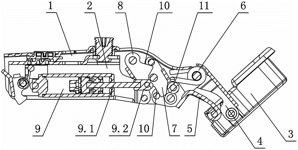
[0033] see Figure 5 The difference from the first embodiment is that the hinge closing working surfaces 10 provided on the pendulum block 8 and the middle pendulum member 7 are all U-groove-shaped planes. Others are not described with the first embodiment.

no. 3 example

[0035] see Image 6 The difference from the first embodiment is that the hinge closing working surface 10 provided on the pendulum block 8 is an open plane, and the hinge closing working surface 10 provided on the middle swinging member 7 is a U-groove-shaped plane. Others are not described with the first embodiment.

no. 4 example

[0037] see Figure 7 The difference from the first embodiment is that the hinge closing working surface 10 provided on the pendulum block 8 is a U-groove-shaped plane, and the hinge closing working surface 10 provided on the middle swinging member 7 is an open plane. Others are not described with the first embodiment.


PUM


Abstract

The invention discloses a driving device used for a hinge and capable of adjusting an arm of force by rotating around a shaft. The driving device comprises an outer rocker arm, an inner rocker arm and a connecting arm and a movable cup seat which are connected through the outer rocker arm and the inner rocker arm, wherein a damper is arranged in the connecting arm; the hinge is internally provided with at least a torsion spring for generating an opening and closing functional force for the movable cup seat; the driving device is characterized in that the damper is a pressure damper with one end per se arranged inside the connecting arm and the other end per se connected to a swing block at least in a hinge closing process; a middle swing member is arranged between the swing block and the inner rocker arm; a pin shaft rotationally connected to the connecting arm is arranged in the middle of the middle swing member; and the middle swing member, the swing block and / or the inner rocker arm are mutually connected in a sliding or rolling manner at least in the hinge closing process. The damper in the invention is a pressure damper; the middle swing member is arranged between the swing block and the inner rocker arm; and the swing block, the inner rocker arm and the middle swing member are connected mutually in the sliding or rolling manner at least in the hinge closing process. Therefore, the driving device used for the hinge and capable of adjusting the arm of force by rotating around the shaft reduces force finally functioned on the damper through force delivery among the swing block, the inner rocker arm and the middle swing member along with the closing of the hinge, and consequently prolongs the service life of the damper.

Description

technical field [0001] The invention relates to a driving device, in particular to a driving device used for a hinge and a rotating and adjusting force arm around an axis. Background technique [0002] The Chinese patent literature number is CN201695827U, which discloses a furniture hinge on January 5, 2011, which includes a fixed arm and a movable cup holder connected by a swing arm assembly. The hinge is provided with a spring that at least generates a closing force on the movable cup holder. It is characterized in that the spring is composed of at least two stages of a main spring and an auxiliary spring. It is said that the invention sets more than two stages of springs in the hinge, so that when the hinge is opened or closed to a certain angle, the hinge can be fully opened or closed automatically through the resultant force of the springs at all stages. , the force of the hinge action is borne by the springs of each level respectively, thus greatly improving the servi...

Claims


Application Information

Patent Timeline
Patent Type & Authority Patents(China)
IPC IPC(8): E05D3/06E05D5/02E05F3/20
Inventor 伍志勇
Owner 伍志勇
Why Eureka
Try Eureka