Ultraviolet, visible and near-infrared light three-band optical imaging system

An optical imaging system, a technology in the ultraviolet band, applied in optics, optical components, instruments, etc., can solve the problems of large system volume, poor imaging quality, low image resolution, etc., to improve imaging quality and image resolution, The effect of reduced size, high image quality and image resolution

Inactive Publication Date: 2012-01-18
CHANGCHUN INST OF OPTICS FINE MECHANICS & PHYSICS CHINESE ACAD OF SCI
View PDF4 Cites 31 Cited by
  • Summary
  • Abstract
  • Description
  • Claims
  • Application Information

AI Technical Summary

Problems solved by technology

[0004] The present invention solves the problem that the incident light beam of the existing multi-band imaging system passes through the same optical mirror group and splits light with a prism to obtain poor imaging quality in each band, low image resolution, and large system volume that is difficult to meet the strict requirements on the system volume. To solve the problem of the occasion, provide a three-band optical imaging system of ultraviolet, visible light and near-infrared

Method used


Image

  • Ultraviolet, visible and near-infrared light three-band optical imaging system
  • Ultraviolet, visible and near-infrared light three-band optical imaging system
  • Ultraviolet, visible and near-infrared light three-band optical imaging system

Examples


specific Embodiment approach 1

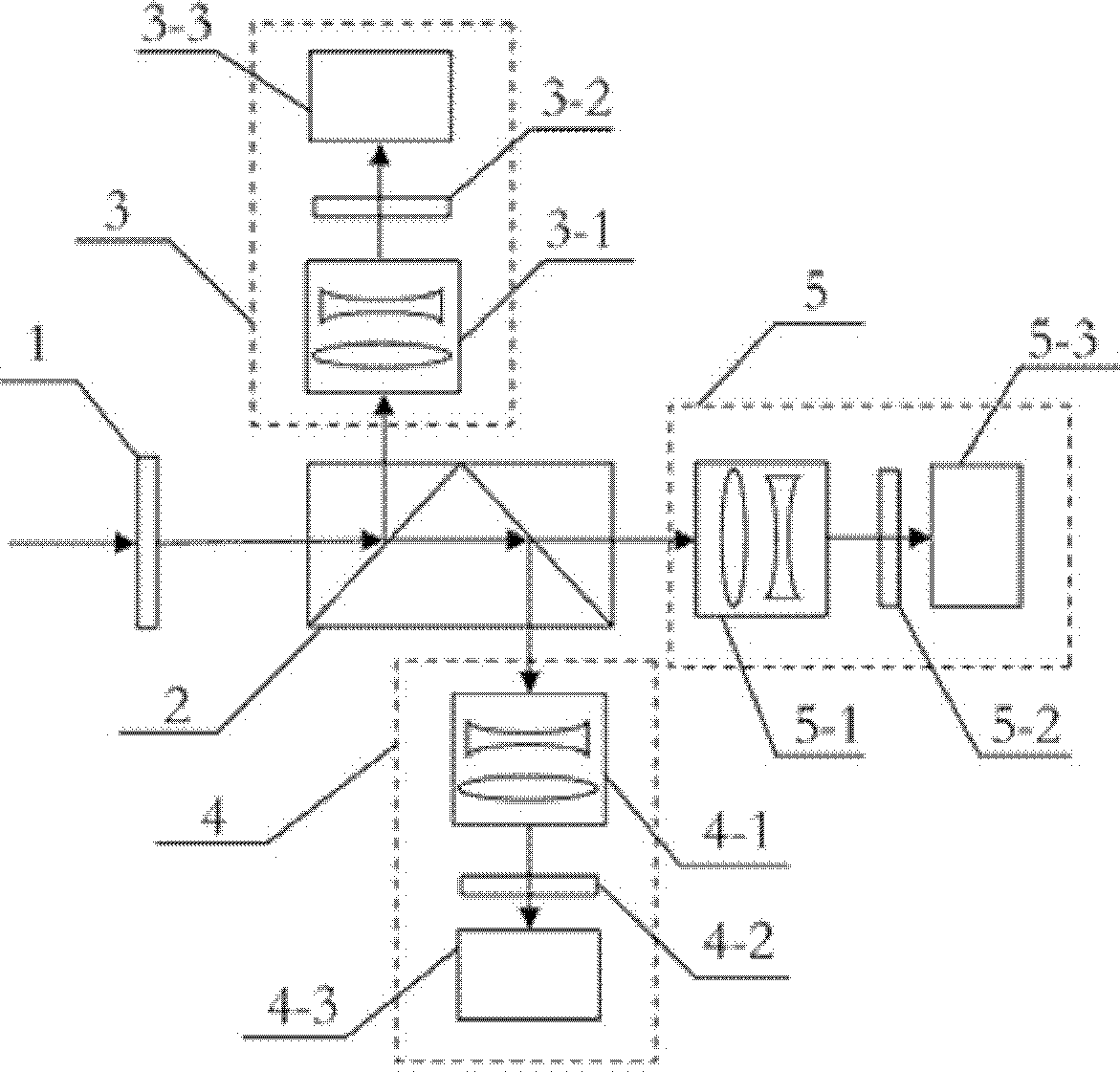
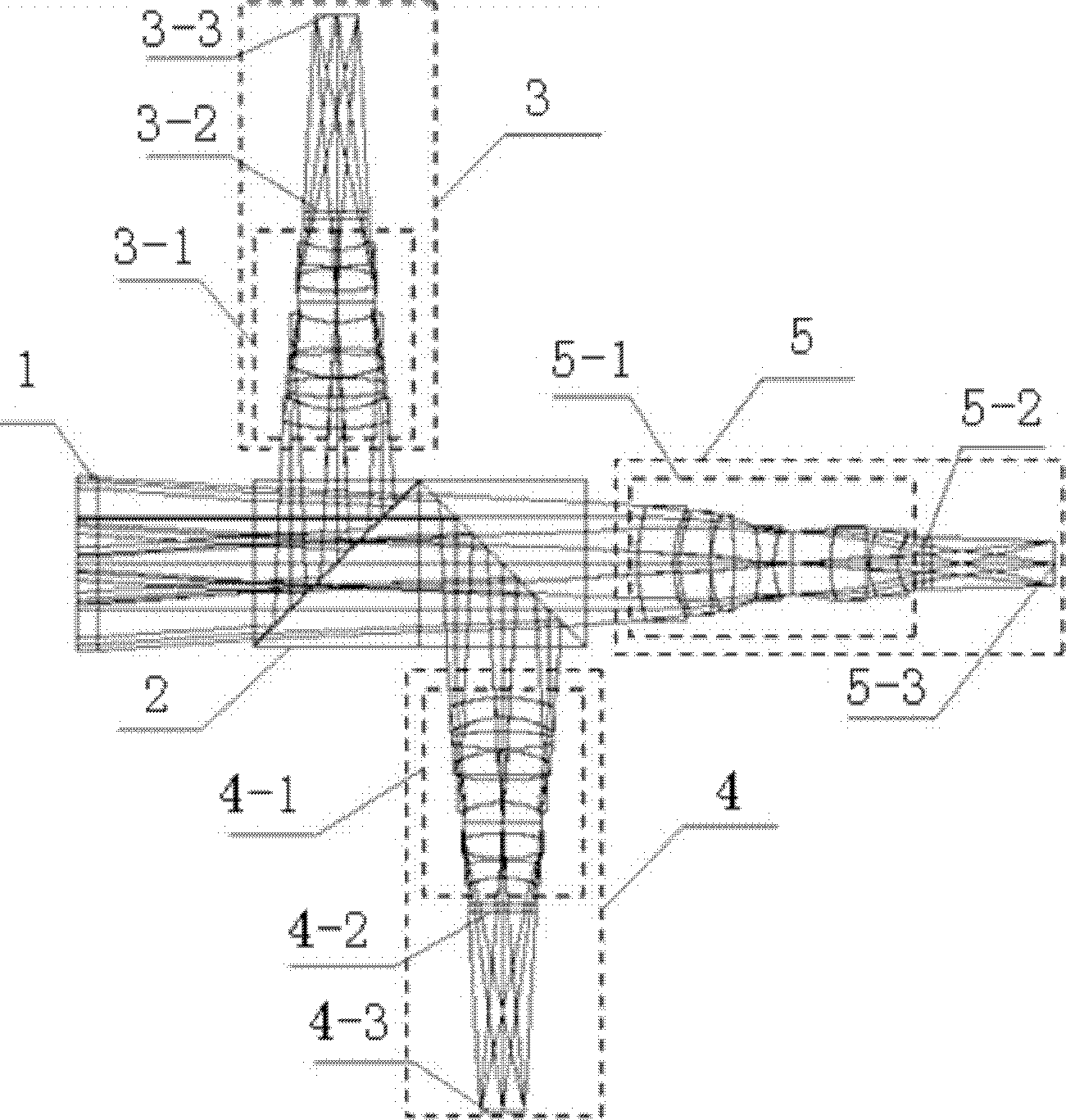
[0012] Specific implementation mode 1. Combination figure 1 Describe this embodiment, the ultraviolet, visible light and near-infrared three-band optical imaging system, the system includes a glass window 1, a three-band beamsplitter prism 2, an ultraviolet band system 3, a visible light band system 4 and a near-infrared band system 5; the target beam passes through the glass Window 1 transmits and enters the three-band beamsplitter prism 2, reflects the ultraviolet beam on the first glued surface of the three-band beamsplitter prism 2, transmits the visible light beam and the near-infrared beam, and the reflected ultraviolet beam enters the ultraviolet band system 3 to form an ultraviolet band image of the target The visible light beam and the near-infrared beam transmitted through the first glued surface of the three-band beamsplitter prism 2 arrive at the second glued surface of the three-band beamsplitter prism 2, and the second glued surface of the three-band beamsplitter ...

specific Embodiment approach 2

[0017] Specific embodiment two, combine figure 2 Describe this implementation mode, this implementation is an embodiment of the ultraviolet, visible light and near-infrared three-band optical imaging system described in the first specific implementation mode:

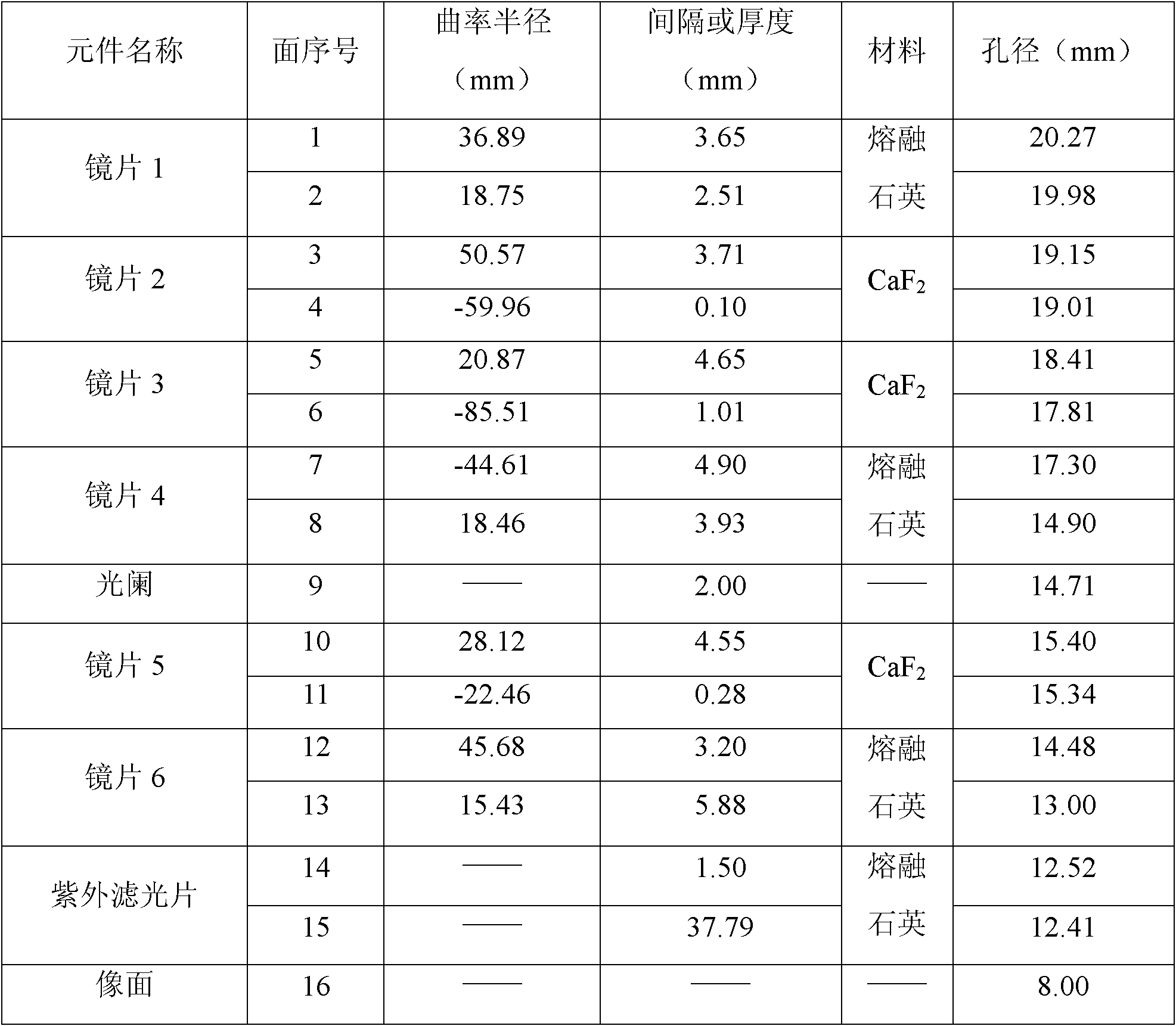
[0018] The technical indicators of the three-band optical imaging system described in this embodiment are as follows:

[0019] Working band: ultraviolet band: 0.30~0.38μm; visible light band: 0.40~0.65μm; near infrared band: 0.76~1.0μm;

[0020] Focal length: the focal length of the three bands is 65mm;

[0021] Field of view: the field of view of the three bands is 7°;

[0022] Resolution: The resolution of the three bands is better than 0.15mrad;

[0023] The glass window 1 and the three-band dichroic prism 2 in this embodiment must be made of glass materials with high transmittance in the wavelength range of 0.3-1.0 μm, and the glass window 1 and the three-band dichroic prism 2 are made of fused silica material. ...


PUM


Abstract

The invention discloses an ultraviolet, visible and near-infrared light three-band optical imaging system relating to an optical imaging system. The invention solves the problems of poor imaging quality of each waveband, low image resolution and large system volume and difficulty in meeting the strict requirement of the system volume because incident light beams of the traditional multi-band imaging system pass through the same optical lens subassembly and decomposed by using a prism. A target light beam transmits through a glass window to a three-band decomposition prism, reflects an ultraviolet light beam on a first gluing surface of the three-band decomposition prism and then enters an ultraviolet band system to form a target ultraviolet band image; the transmitted visible light beam and near-infrared light beam enter a visible light band system after the visible light beam is reflected by a second gluing surface to form a target visible light band image; and the transmitted near-infrared light beam enters to a near-infrared band system to form a target near-infrared band image. The ultraviolet, visible and near-infrared light three-band optical imaging system can obtain image information of a target in three bands at the same time, and is suitable for the field of industrial detection.

Description

technical field [0001] The invention relates to an optical imaging system, in particular to an optical imaging system of ultraviolet, visible light and near-infrared three-wave bands using a prism to split light. Background technique [0002] With the rapid development of science and technology, in many occasions of industrial detection, in order to accurately detect the target, it is necessary to obtain the spectral information of the target's ultraviolet, visible light and near-infrared bands. [0003] At present, the existing multi-band imager or three-band imaging system generally adopts the following two technical solutions: The first solution uses multiple optical apertures to form an optical system respectively. This solution has a large system volume and is difficult to apply to volume Strict application occasions; the second solution uses common optical aperture. After the incident beam passes through the same optical mirror group, it is split by a prism or a beam s...

Claims


Application Information

Patent Timeline
Patent Type & Authority Applications(China)
IPC IPC(8): G02B27/00G02B27/10G01J3/28
Inventor 郭帮辉孙强王健周怀得李广泽刘金国郭永飞
Owner CHANGCHUN INST OF OPTICS FINE MECHANICS & PHYSICS CHINESE ACAD OF SCI
Why Eureka
Try Eureka