
Waterway cooling structure of back mould

A technology of cooling structure and water circuit, applied in the field of cooling structure of mold, can solve the problems of prolonging mold molding cycle, affecting product quality, unable to design cooling water circuit, etc., to achieve the effect of ensuring cooling and ensuring quality

Inactive Publication Date: 2012-01-25
VANGUARD TECH WUXI
View PDF0 Cites 3 Cited by
  • Summary
  • Abstract
  • Description
  • Claims
  • Application Information

AI Technical Summary

Problems solved by technology

[0002] The existing water cooling structure of the rear mold is usually affected by structural features such as screw holes, thimble holes, and insert holes during the design process, which limits the cooling water design
Especially for some parts that need to be cooled by cooling water, due to the influence of thimble holes and screw holes, the cooling water path cannot be designed. If the cooling water is not designed, the molding cycle of the mold will be prolonged and the quality of the product will be affected.

Method used


Image

  • Waterway cooling structure of back mould
  • Waterway cooling structure of back mould

Examples


Embodiment Construction

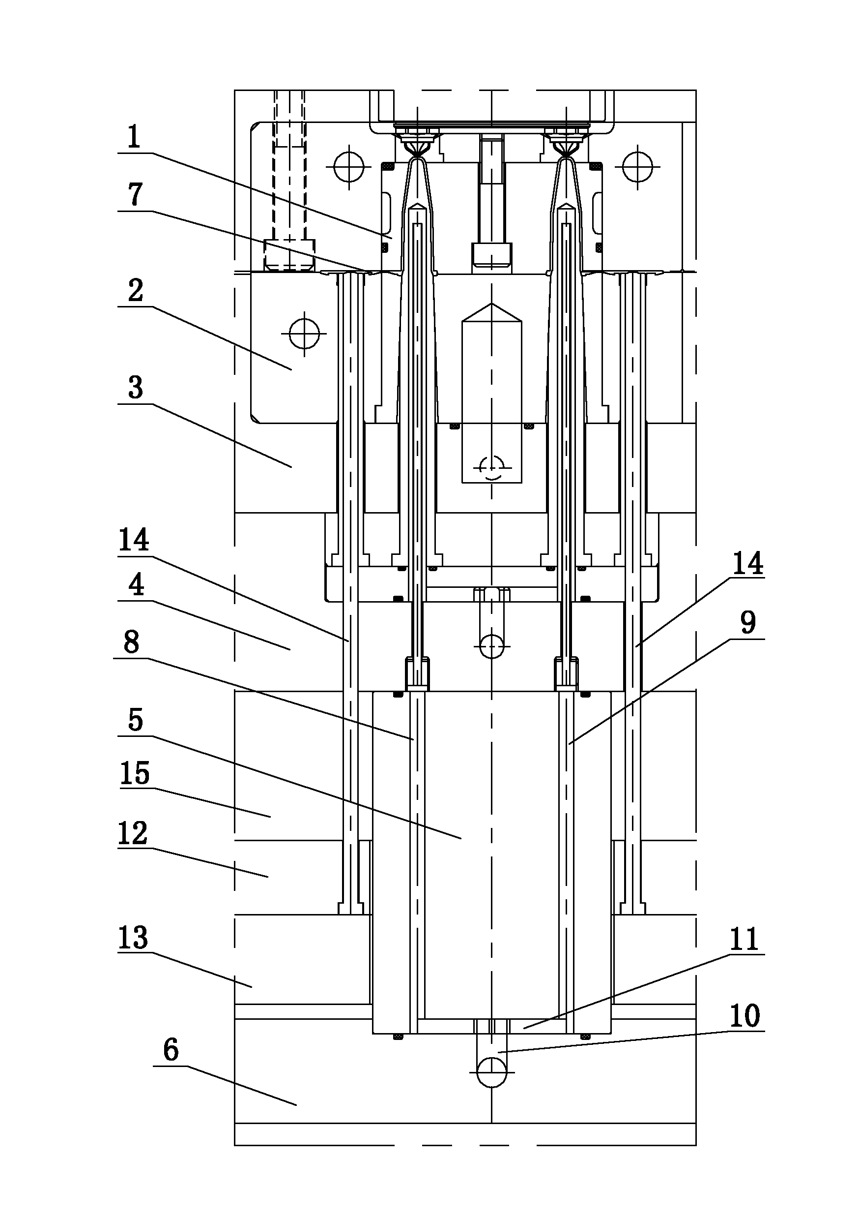
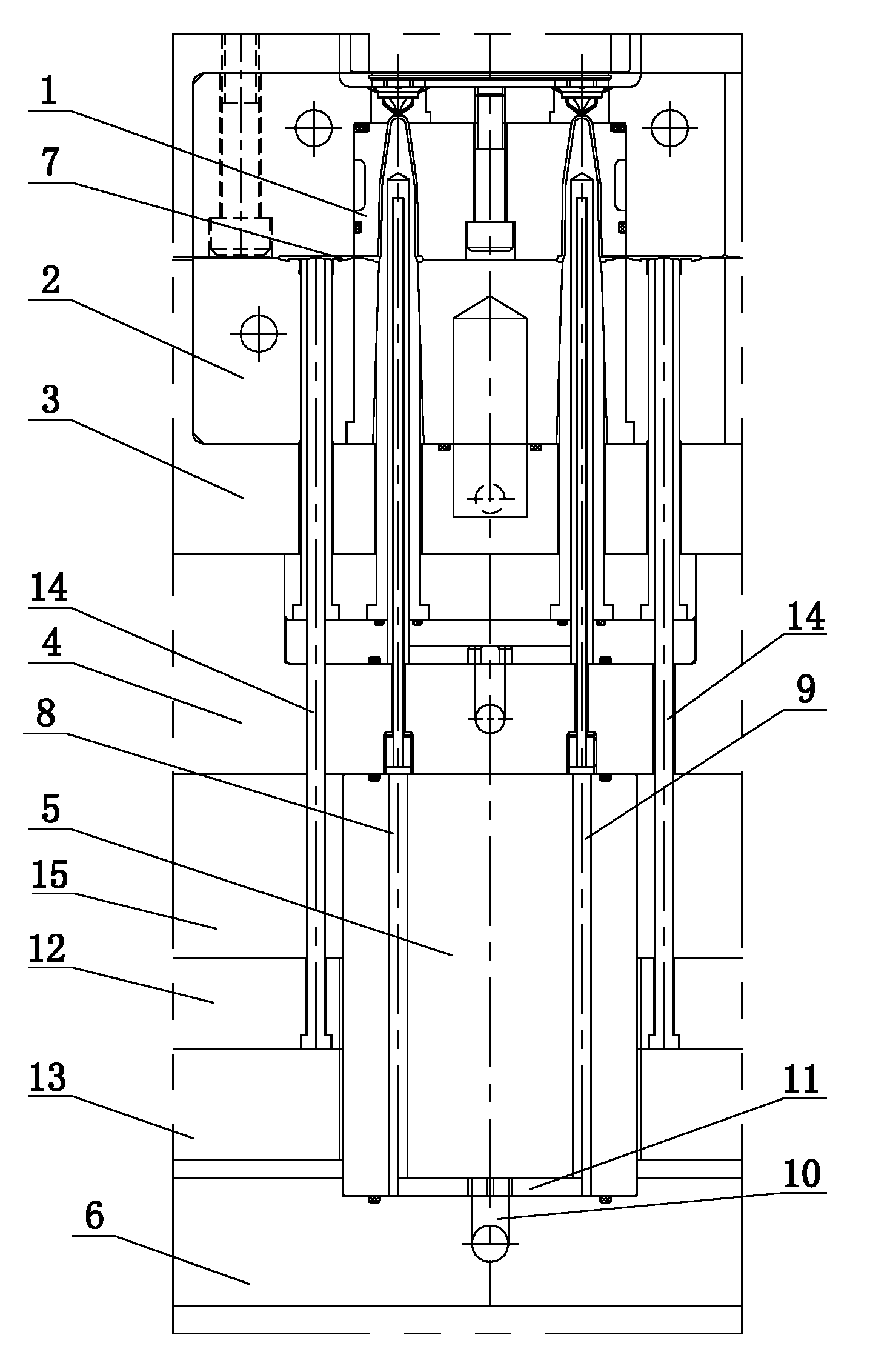
[0009] See figure 1 , which includes a front mold core 1, a rear mold core 2, a B plate 3, a backing plate 4, a support column 5, and a lower fixing plate 6. Formed product 7, the rear model core 2 is supported on the B plate 3, the B plate 3 is supported on the backing plate 4, the backing plate 4 is supported on the support column 5, the support column 5 is supported on the lower fixed plate 6, and the waterways 8 and 9 are from bottom to top After passing through the support column 5, backing plate 4, and B plate 3 in sequence, it goes deep into the interior of the rear model core 1, and the lower fixed plate 6 is provided with a water pipe channel 10, and the inner side of the water pipe channel 10 is connected to the bottom of the waterways 8, 9, specifically the waterways 8, The bottom between 9 is provided with a communication groove 11, and the communication groove 11 communicates with the water pipe passage 10; the outside of the water pipe passage 10 is connected wit...


PUM


Abstract

The invention provides a waterway cooling structure of a back mould, which is used for enabling a design to be free of the limitation of a screw hole, an ejector pin hole and an insert hole, ensuring the normal arrangement of the design, and further ensuring the cooling of the back mould and the quality of a product. The waterway cooling structure of the back mould comprises a front mould core, a back mould core, a plate B, a base plate, a support pillar and a lower fixed plate, wherein the front mould core and the back mould core are mutually matched to form a diccavity; the back mould core is supported on the plate B; the base plate is supported on the support pillar; and the support pillar is supported on the lower fixed plate. The waterway cooling structure of the back mould is characterized in that: waterways sequentially penetrate through the support pillar, the base plate, the plate B from bottom to top so as to penetrate into the back mould core; a water pipe channel is formed on the lower fixed plate; the inner side of the water pipe channel is connected with the tops of the waterways; and the outer side of the water pipe channel is connected with cooling water.

Description

technical field [0001] The invention relates to the technical field of mold cooling structures, in particular to the water cooling structure of a rear mold. Background technique [0002] The existing water channel cooling structure of the rear mold is usually affected by structural features such as screw holes, thimble holes, and insert holes during the design process, which limits the design of the cooling water channel. Especially for some parts that need to be cooled by cooling water, due to the influence of thimble holes and screw holes, it is impossible to design cooling water channels. If cooling water is not designed, the molding cycle of the mold will be prolonged and the quality of the product will be affected. Contents of the invention [0003] The invention provides the water cooling structure of the rear mold, which makes the design not restricted by screw holes, thimble holes, and insert holes, and ensures the normal layout of the design, thereby ensuring the ...

Claims


Application Information

Patent Timeline
Patent Type & Authority Applications(China)
IPC IPC(8): B29C33/04
Inventor 张卫
Owner VANGUARD TECH WUXI
Learn More