Medical image apparatus and medical image archiving apparatus
A medical image and image technology, applied in medical image data management, medical image, image communication, etc., can solve the problems of low performance and simple terminals, and achieve the effect of diagnosis support and smooth film reading
- Summary
- Abstract
- Description
- Claims
- Application Information
AI Technical Summary
Problems solved by technology
Method used
Image
Examples
no. 1 Embodiment approach
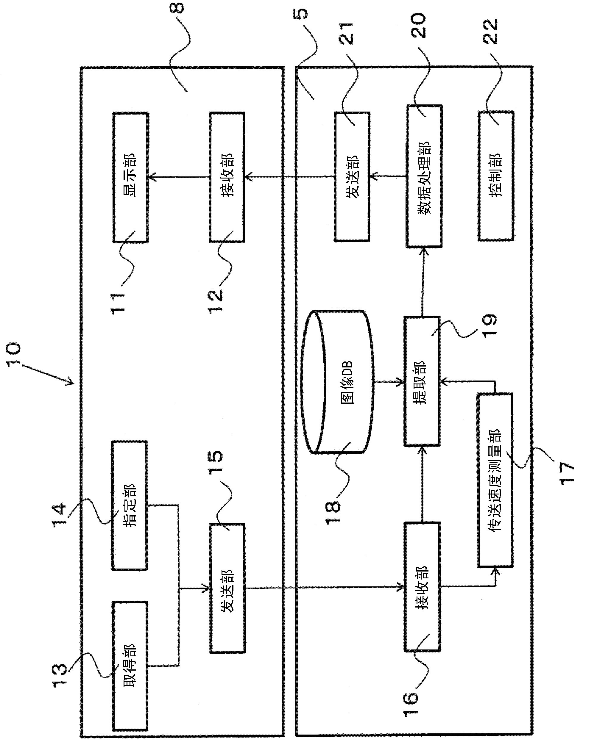
[0032] use Figure 2 to Figure 4B The configuration of the medical imaging device according to the first embodiment will be described in detail.
[0033] figure 2 It is a diagram showing the configuration of a medical image device 10 composed of a medical image storage device 5 and a medical image utilization device 8 . In addition, the medical image utilization device 6 also has the same configuration as the medical image utilization device 8 .
[0034] (Structure of Medical Image Utilization Device)
[0035] The medical image utilization device 8 has a display unit 11 , a reception unit 12 , an acquisition unit 13 , a designation unit 14 , and a transmission unit 15 .
[0036] The display unit 11 has a function of displaying medical images captured by the medical imaging device 4 . The medical image is transmitted, for example, from the medical image storage device 5 (image DB 18 described later) via the receiving unit 12 .
[0037] The acquiring unit 13 has a function...
no. 2 Embodiment approach
[0068] Next, use Figure 5 and Figure 6 The configuration of the medical imaging device according to the second embodiment will be described in detail. In addition, description of the same configuration as that of the first embodiment is omitted.
[0069] The second embodiment differs from the first embodiment in that an actual frame rate is used instead of a data transfer rate when extracting an area displayed at a requested frame rate.
[0070] Therefore, in the second embodiment, if Figure 5 As shown, an actual frame rate measurement unit 25 is provided in the medical image storage device 5 .
[0071] The actual frame rate measurement unit 25 has a function of measuring the actual frame rate when the display unit 11 of the medical image utilization device 8 actually performs animation display. Here, the "actual frame rate" refers to a value indicating how many times per second the medical image transmitted from the medical image storage device 5 is actually updated on...
no. 3 Embodiment approach
[0086] Next, use Figure 7 The processing related to the third embodiment will be described in detail.
[0087] In the first embodiment and the second embodiment, when updating an image of a predetermined area at a requested frame rate, it may be necessary to confirm whether the predetermined area is within the range desired by the radiologist before starting the image update. . The third embodiment relates to processing to satisfy such a request. In addition, the following description is based on the processing of the first embodiment, but the processing of this embodiment can also be applied to the second embodiment.
[0088] When a radiographer requests a medical image of a certain subject from a medical image utilization device 8 at home or the like via the out-of-hospital network 9, the image DB 18 stores a part of medical images (multiple pieces) that meet the request. part of the medical image) is sent to the medical image utilization device 8 . As a result, a part ...
PUM
 Abstract
Description
Claims
Application Information
 - R&D
- Intellectual Property
- Life Sciences
- Materials
- Tech Scout
- Unparalleled Data Quality
- Higher Quality Content
- 60% Fewer Hallucinations
Browse by: Latest US Patents, China's latest patents, Technical Efficacy Thesaurus, Application Domain, Technology Topic, Popular Technical Reports.
© 2025 PatSnap. All rights reserved.Legal|Privacy policy|Modern Slavery Act Transparency Statement|Sitemap|About US| Contact US: help@patsnap.com


