Tape cartridge and tape printer

A technology with printing and cassettes, applied in the directions of printing devices, ink ribbon cassettes, and inking devices, etc., can solve the problems of inability to abut the thermal head.

Active Publication Date: 2012-02-01
SEIKO EPSON CORP +1
View PDF6 Cites 20 Cited by
  • Summary
  • Abstract
  • Description
  • Claims
  • Application Information

AI Technical Summary

Problems solved by technology

Therefore, there is a problem that the thermal head cannot be abutted (pressed) against the pressure

Method used


Image

  • Tape cartridge and tape printer
  • Tape cartridge and tape printer
  • Tape cartridge and tape printer

Examples


Embodiment Construction

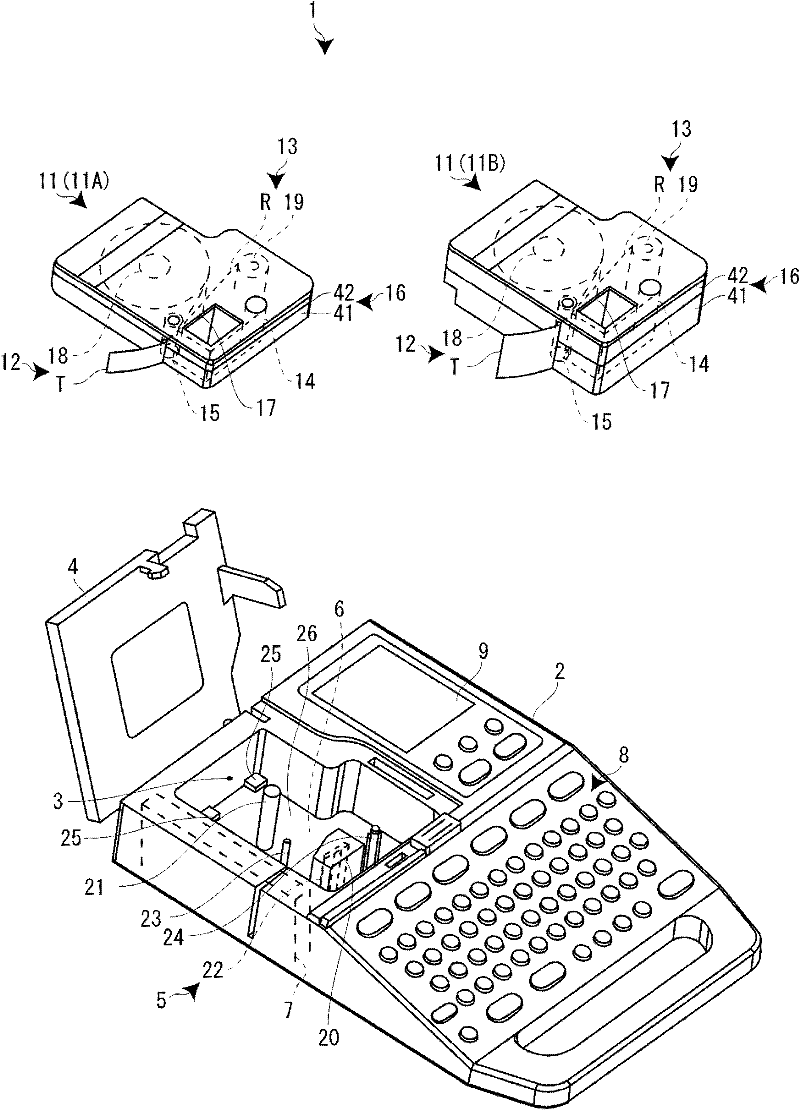
[0027] Hereinafter, a tape cassette according to an embodiment of the present invention and a tape printing apparatus mounted with the tape cassette will be described with reference to the drawings. This tape printing device performs printing while conveying a printing tape and an ink ribbon from an attached tape cassette, and cuts the printed portion of the printing tape to form a label (tape sheet).

[0028] Such as figure 1 As shown, the tape printing device 1 has: a casing 2 forming a casing; a cassette mounting portion 3 (tape mounting portion) is recessed and formed on the upper surface of the casing 2, and a printing tape T etc. is detachably mounted and housed therein. The tape cassette 11; the opening and closing cover 4, which opens and closes the cassette installation part 3; the printing mechanism 5, which has the print head 22 vertically arranged in the cassette installation part 3, and prints the printing tape T; the tape feeding mechanism 6 , which feeds the pr...


PUM


Abstract

The invention provides a tape cartridge and a tape printer, in which it is unnecessary to perform a seat-entering adjustment on a printer head relative to a lower end. The tape cartridge includes a platen roller 15, when the tape cartridge is mounted on a tape printer 1, a print head 22 of the tape printer 1 contacting the platen roller 15 with a print tape T and an ink ribbon R arranged therebetween such that the print head 22 can be separated from the platen roller 15; a cartridge case 16 that houses the print tape T, the ink ribbon R, and the platen roller 15; and an insertion opening 17 formed in the cartridge case 16, the print head 22 being inserted into the insertion opening 17. A contact portion 10 of the platen roller 15 that is brought into contact with the print head 22 protrudes relative to a head receiver 72 of the insertion opening 17 to which the print head 22 is exposed.

Description

technical field [0001] The present invention relates to a tape cassette and a tape printing device detachably mounted on a tape printing device. Background technique [0002] In the past, as such a tape cassette, the following tape cassettes are known. The thermal head is pressed sideways to be in a printing state (refer to Patent Document 1). [0003] The tape cassette is externally formed by a cassette case composed of an upper case and a lower case on the seat side. An upper through opening through which the thermal head penetrates is formed in the upper case, and a lower through opening through which the thermal head penetrates is formed in the lower case. The upper through-opening is formed so that the contacted portion of the pressure roller that the thermal head contacts protrudes, and the lower through-opening is formed slightly protruding from the upper through-opening so that the contacted portion of the pressure roller does not protrude. This prevents the ink r...

Claims


Application Information

Patent Timeline
IPC IPC(8): B41J32/00
CPCB41J3/4075B41J15/044B41J2/325B41J3/36B41J32/00B41J15/04
Inventor 袖山秀雄
Owner SEIKO EPSON CORP
Why Eureka
Try Eureka