Blade spraying protective fixture

A technology of protective clips and blades, applied in the direction of spraying devices, can solve problems such as bridging, achieve high spraying efficiency, save manpower and material costs, and not easily shift or shake

Active Publication Date: 2017-09-08
CHINA HANGFA SOUTH IND CO LTD
View PDF6 Cites 16 Cited by
  • Summary
  • Abstract
  • Description
  • Claims
  • Application Information

AI Technical Summary

Problems solved by technology

[0005] The invention provides a blade spray protection fixture to solve the technical problem that the existing blade protection fixture is prone to form a "bridge" phenomenon between the sprayed trailing edge plate and the fixture, and the levelness of the edge plate needs to be continuously adjusted during the spraying process.

Method used


Image

  • Blade spraying protective fixture
  • Blade spraying protective fixture
  • Blade spraying protective fixture

Examples


Embodiment Construction

[0031] The embodiments of the present invention will be described in detail below with reference to the accompanying drawings, but the present invention can be implemented in many different ways defined and covered by the claims.

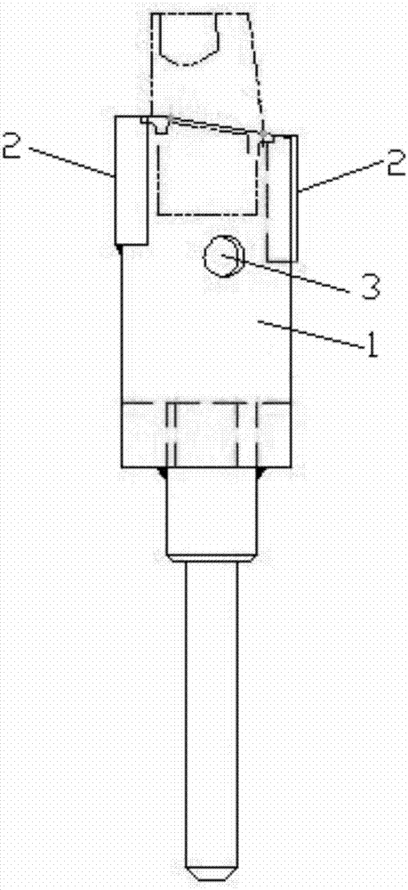
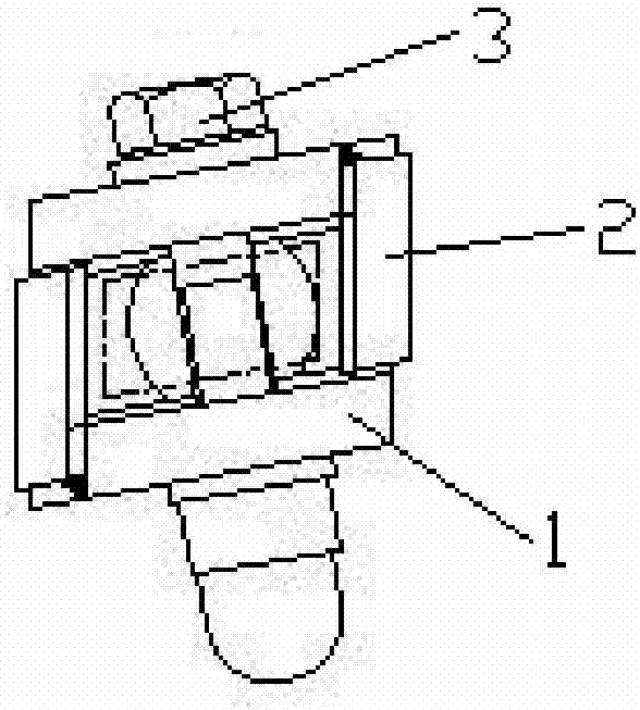
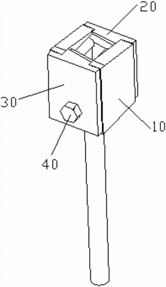
[0032] refer to Figure 3 to Figure 5 , the preferred embodiment of the present invention provides a blade spraying protective fixture, which is used to connect to the spraying equipment to protect the lower surface and the tenon of the blade edge plate when the blade is sprayed. The blade spraying protective fixture includes: used for spraying The fixture body 10 connected to the equipment, the fixture body 10 is provided with an accommodation groove 101 for accommodating the tenon, the accommodation groove 101 runs through the two side walls of the fixture body 10 and communicates with the upper end surface of the fixture body 10, the accommodation groove 101 The two side walls of the blade are symmetrically provided with positioning flanges 102 t...


PUM


Abstract

The invention discloses a blade spraying protective fixture which is used for being connected to spraying equipment so as to protect the lower surface of a blade edge plate and a tenon. The blade spraying protective fixture comprises a fixture body, a first stopping block, a second stopping block and locking pieces, wherein the fixture body is used for being connected with the spraying equipment and provided with a containing groove used for containing the tenon; the containing groove penetrates through the two side walls of the fixture body and communicates with the upper end surface of the fixture body; outwards convex positioning flanges extending in the length direction of the containing groove are symmetrically arranged on the two side walls of the containing groove so as to be used for supporting and positioning the long edges of the blade edge plate and enabling the upper surface of the blade edge plate to be exposed out of the upper end surface of the fixture body; the first stopping block and the second stopping block are arranged at the two ends in the length direction of the containing groove correspondingly so as to be used for blocking the two ends of the containing groove and being matched with the positioning flanges to support and position the short edges of the blade edge plate; the first stopping block and the second stopping block are both partially embedded in the containing groove and abut against the tenon located in the containing groove so as to clamp and fix the tenon; and the locking pieces are used for locking the first stopping block and the second stopping block with the fixture body.

Description

technical field [0001] The invention relates to the field of blade spraying, in particular to a blade spraying protective fixture. Background technique [0002] Vacuum plasma spraying is the plasma spraying that places the workpiece, turntable, spray gun, etc. in a closed vacuum chamber. Vacuum plasma spraying avoids oxidation in the atmospheric environment, and the cleaning effect of the transferred arc can make the surface of the workpiece cleaner, which is beneficial to the coating and coating. Therefore, vacuum plasma spraying technology is widely used in aero-engine turbine components, which has better resistance to high-temperature oxidation, high-temperature corrosion, and high-temperature sealing. [0003] The turbine working blade of a certain type is vacuum plasma sprayed with nickel-cobalt-chromium-aluminum-yttrium-tantalum coating. The process requires spraying the entire blade body and the upper surface of the edge plate. The thickness of the coating is controll...

Claims


Application Information

Patent Timeline
Patent Type & Authority Applications(China)
IPC IPC(8): B05B13/02B05B15/04
CPCB05B13/0285
Inventor 陈建强赵伟志姬小兰郭志宏云海涛张汝周琴刘芳张志远张卫红
Owner CHINA HANGFA SOUTH IND CO LTD
Why Eureka
Try Eureka