Micro-sprinkling belt spreading and rolling dual-purpose machine

A micro-spray belt and dual-purpose technology, which is applied in the field of water-saving irrigation auxiliary machinery, can solve the problems of deflection of the micro-spray belt, low labor and production efficiency, time-consuming, etc. good stability

Active Publication Date: 2015-04-29
SHANDONG AGRICULTURAL UNIVERSITY
View PDF8 Cites 6 Cited by
  • Summary
  • Abstract
  • Description
  • Claims
  • Application Information

AI Technical Summary

Problems solved by technology

[0003] One is that the nozzle holes of the micro-spray belt are only distributed on one side of the belt body, which often leads to the deviation of the micro-spray belt body due to rough ground and unevenness, especially when the spray angle of the micro-spray belt (the angle of the jet water at the nozzle hole) When the angle between the tangent and the horizontal plane) is narrow, the sprayed water flow is seriously deflected, reducing the uniformity of irrigation water distribution, which not only affects the water saving effect, but also leads to crop yield reduction
[0004] The second is that after the micro-spray belt is used, there is often residual water in the belt. When it is rolled up, it needs to be manually drained by pulling the water before it can be rolled up. Time-consuming, laborious, hard work, and low labor and production efficiency
However, these two mechanical devices only have the function of retracting the micro-spray belt, and cannot lay the micro-spray belt, let alone solve the problems of deflection of the micro-spray belt and uneven water spray caused by uneven ground; The belt is also pulled hard on the micro-spray belt, causing a lot of wear and tear

Method used


Image

  • Micro-sprinkling belt spreading and rolling dual-purpose machine
  • Micro-sprinkling belt spreading and rolling dual-purpose machine

Examples


Embodiment Construction

[0025] Specific embodiments of the present invention will be described below in conjunction with the accompanying drawings.

[0026] This specific embodiment is only an explanation of the present invention, not a limitation of the present invention. After reading this specification, those skilled in the art can make modifications to this embodiment without creative contribution as required, but as long as they are within the rights of the present invention All claims are protected by patent law.

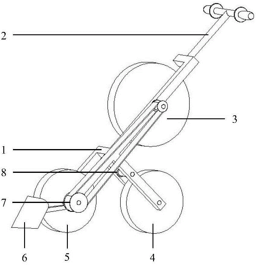
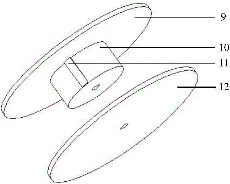
[0027] Examples see attached figure 1 , a dual-purpose machine for laying and winding micro-spray tape, including a frame, a steering handle, a winding wheel, a crawler wheel, a pressing wheel, a scraper, a transmission device and a guide wheel; the track wheel, the pressing wheel, the winding wheel and The width of the guide wheel can be determined according to the width of the micro-spray belt. The width of the track wheel, pressing wheel, take-up wheel and guide wheel is the same...


PUM


Abstract

The invention relates to a micro-sprinkling belt spreading and rolling dual-purpose machine. The micro-sprinkling belt spreading and rolling dual-purpose machine comprises a rack, a steering handle, a tape feed roller, a crawler wheel, a press wheel, a soil scraper, a transmission device and a guide wheel, wherein the rack consists of an upper beam, a long arm and two forked structures which are connected into an integer from top to bottom in sequence; the forked structures are respectively fixed at front and rear sides of the long arm through a lower beam vertical to the long arm; the two forked structures are respectively used for fixing the crawler wheel and the press wheel; the steering handle is T-shaped; the lower end of the steering handle is connected on the upper beam; the tape feed roller is fixed on the long arm between the lower beam and the upper beam through a wheel shaft; the crawler wheel and the press wheel are mounted on the rack through the wheel shaft; the soil scraper plate is movably connected to the front end of the press wheel through a connecting rod; the guide wheel is arranged behind the rack. The micro-sprinkling belt spreading and rolling dual-purpose machine can realize multiple purposes, is simple in structure, strong in function and good in stability, not only can be used for spreading micro-sprinkling belt, but also can be used for rolling the micro-sprinkling belt, so that the abrasion to the micro-sprinkling belt is reduced, and the service life of the micro-sprinkling belt is prolonged.

Description

technical field [0001] The invention belongs to the technical field of auxiliary machinery for water-saving irrigation, and in particular relates to a multi-functional machine capable of laying the micro-spray belt for irrigation evenly and retracting the water under field conditions. It is suitable for field crops such as wheat and corn and other It is used when plant production is carried out with micro-spray and water-saving irrigation. technical background [0002] The micro-spray belt is a new type of water-saving irrigation equipment with quantitative function. Its working principle is that the pressure water is sent from the water pipe to the micro-spray belt laid in the field, and sprayed through the outlet holes on the micro-spray belt. Under the joint action of gravity and air resistance, a drizzle-like spray effect is formed. The water outlet holes of the micro-spray belt are generally arranged in a porous grouping manner and arranged according to a certain dista...

Claims


Application Information

Patent Timeline
Patent Type & Authority Applications(China)
IPC IPC(8): B65H75/42
Inventor 王东
Owner SHANDONG AGRICULTURAL UNIVERSITY
Why Eureka
Try Eureka