Lifting interbody fusion device and operation device for driving same

A cage and manipulator technology, applied in the field of manipulators, can solve the problems of inability to adjust the vertebral body cage, small internal space, unstable use of the vertebral body cage, etc.

Active Publication Date: 2016-11-30
GUANGZHOU ARNOLD MEDICAL DEVICE CO LTD
View PDF7 Cites 15 Cited by
  • Summary
  • Abstract
  • Description
  • Claims
  • Application Information

AI Technical Summary

Problems solved by technology

[0002] In daily life, cases of vertebral body damage due to tumors, fractures, infections, etc. occur from time to time. When treating these patients, the current method used is to implant a fusion device between the damaged vertebral bodies to make the bone tissue produce Crawling substitutes to repair the damaged vertebral body. However, the height of the traditional vertebral body fusion cage is fixed, and the height of the intervertebral body of the human body varies from person to person. It is impossible to adjust the height of the vertebral body fusion cage to suit the different needs of different patients. Intervertebral height, so that the vertebral body fusion device cannot be fully adapted to the intervertebral height of the human body, which affects the treatment effect
The general vertebral body fusion device with height adjustment function is not stable when used, and the internal space is small, which may easily cause small space for bone grafting during the operation and affect the healing rate

Method used


Image

  • Lifting interbody fusion device and operation device for driving same
  • Lifting interbody fusion device and operation device for driving same
  • Lifting interbody fusion device and operation device for driving same

Examples


Embodiment Construction

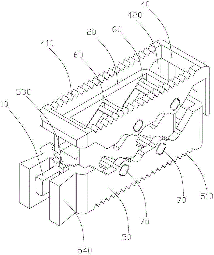
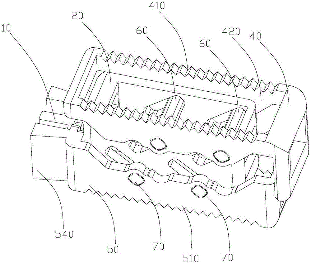
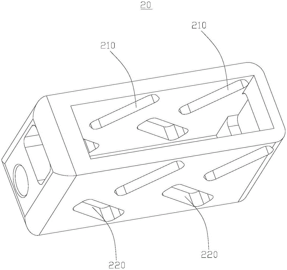
[0032] Such as Figures 1 to 3 As shown, a lifting vertebral body fusion device includes a screw rod 10, a middle limiting frame 20, an upper lifting block 40 and a lower lifting block 50, and the upper lifting block 40 is sleeved on the outer side of the upper part of the middle limiting frame 20. The lower lifting block 50 is sleeved on the outer side of the lower part of the middle limit frame 20, and at least two first chute 210 and at least two second chute 220 are opened on both side walls of the middle limit frame 20, The inclination directions of the first chute 210 and the second chute 220 are opposite, and the side wall of the upper lifting block 40 is provided with a first latch 60 which is slidingly fitted with the first chute 210 , and the lower lifting The side wall of the block 50 is provided with a second latch 70 slidingly fitted with the second chute 220, the screw 10 is screwed to the middle limit frame 20, and the screw 10 is limited on the upper lift. blo...


PUM


Abstract

The invention relates to a lifting interbody fusion device and an operation device for driving the same. The lifting interbody fusion device comprises a screw, a middle limiting frame, an upper lifting block and a lower lifting block. The upper lifting block is arranged on the outer side of the upper portion of the middle limiting frame in a sleeving mode, the lower lifting block is arranged on the outer side of the lower portion of the middle limiting frame in a sleeving mode, at least two first inclined grooves and at least two second inclined grooves are formed in each of the two side walls of the middle limiting frame, the inclination directions of the first inclined grooves and the second inclined grooves are opposite, first bolts in sliding fit with the first inclined grooves are arranged on the slide walls of the upper lifting block, second bolts in sliding fit with the second inclined grooves are arranged on the slide walls of the lower lifting block, and the screw is connected with the middle limiting frame through threads and limited on the upper lifting block or the lower lifting block. The interbody fusion device is adjustable in height and stable in use; besides, the inner space of the interbody fusion device is large, the bone grafting space in an operation is large, the bone grafting quantity is large, and the healing success rate is high.

Description

technical field [0001] The invention relates to the field of medical devices, in particular to an elevating vertebral body fusion device and an operator for driving the elevating vertebral body fusion device. Background technique [0002] In daily life, cases of vertebral body damage due to tumors, fractures, infections, etc. occur from time to time. When treating these patients, the current method used is to implant a fusion device between the damaged vertebral bodies to make the bone tissue produce Crawling substitutes to repair the damaged vertebral body. However, the height of the traditional vertebral body fusion cage is fixed, and the height of the intervertebral body of the human body varies from person to person. It is impossible to adjust the height of the vertebral body fusion cage to suit the different needs of different patients. Intervertebral height, so that the intervertebral height of the human body cannot be fully applied to the vertebral fusion device, whic...

Claims


Application Information

Patent Timeline
Patent Type & Authority Applications(China)
IPC IPC(8): A61F2/44A61F2/46A61F2/48
CPCA61F2/4455A61F2/4611A61F2002/30329A61F2002/30537A61F2002/4625A61F2002/4688A61F2/48
Inventor 赵汝琛成朝福
Owner GUANGZHOU ARNOLD MEDICAL DEVICE CO LTD
Why Eureka
Try Eureka