Switching power supply device

a power supply device and power supply technology, applied in the field of switching power supply devices, can solve the problems of increasing the power loss in the power detection circuit, large space and great cost, and requiring large space and great cost, and achieve the effect of improving the power conversion efficiency

Inactive Publication Date: 2007-06-28
SANKEN ELECTRIC CO LTD
View PDF9 Cites 76 Cited by
  • Summary
  • Abstract
  • Description
  • Claims
  • Application Information

AI Technical Summary

Benefits of technology

[0008] While power factor correction circuits are capable of active control of power factor correction in response to an increase of power consumption in an external load, a nominal-rated voltage for an AC power supply varies greatly depending on a country (e.g., 100 VAC in Japan, 115 VAC in U.S., and 230 VAC in European countries). Therefore, it has been difficult for a power supply device, which is adaptable to different nominal AC supply voltages of various countries, to enable a PFC circuit when a load power reaches a predetermined level in response to an increase of power consumption in an external load and to disable the PFC circuit when a load power falls to the predetermined level or lower in response to a decrease of power consumption in the external load, while improving power conversion efficiency at each rated load (or steady load) over the wide range of input voltage.

Problems solved by technology

Therefore, it has been difficult for a power supply device, which is adaptable to different nominal AC supply voltages of various countries, to enable a PFC circuit when a load power reaches a predetermined level in response to an increase of power consumption in an external load and to disable the PFC circuit when a load power falls to the predetermined level or lower in response to a decrease of power consumption in the external load, while improving power conversion efficiency at each rated load (or steady load) over the wide range of input voltage.
However, in a method of detecting a level of load power at the secondary side, generally a large quantity of current is supplied in a normal operation mode, which increases a power loss in a power detection circuit.
When a current transformer is employed to suppress the power loss in the power detection circuit, a large space and great cost are required.
Since this method requires additional components to transmit a signal from the secondary side to a primary side, a larger space and greater cost are required, which makes miniaturization and cost reduction difficult.
However, power levels detected at the primary side are not in complete proportion to actual output power levels because of variations in an input voltage.
Since detected load power levels for use in determination as to enabling or disabling the PFC circuit thus vary due to variations in the input voltage, enabling or disabling the PFC circuit fails within a rated power in some cases.
In particular, when a load condition is detected based on a duty ratio of a control signal of a switching element in a PFC circuit or when a control operation is performed to vary an output voltage in accordance with a variation in an input voltage to maximize conversion efficiency at a small input voltage, variations in an input voltage result in significantly deviated detection of a load power.
Since turning on and off of the PFC circuit is disabled in a given load condition, power conversion efficiency in a standby or light-load mode is extremely deteriorated to fail to meet the EPA's specifications that require average power conversion efficiency of 84% or greater at each of output load factors of 25%, 50%, 75%, and 100%.
Since the relevant power supply device uses the active PFC circuit, switching losses in a switching element or losses in an electronic circuit controlling the switching element deteriorate the overall power efficiency under light load condition.
Consequently, a power loss is increased (power losses increase in proportion to current squared) due to an increase of an input current to the PFC circuit, thereby deteriorating the efficiency.

Method used


Image

  • Switching power supply device
  • Switching power supply device
  • Switching power supply device

Examples


first embodiment

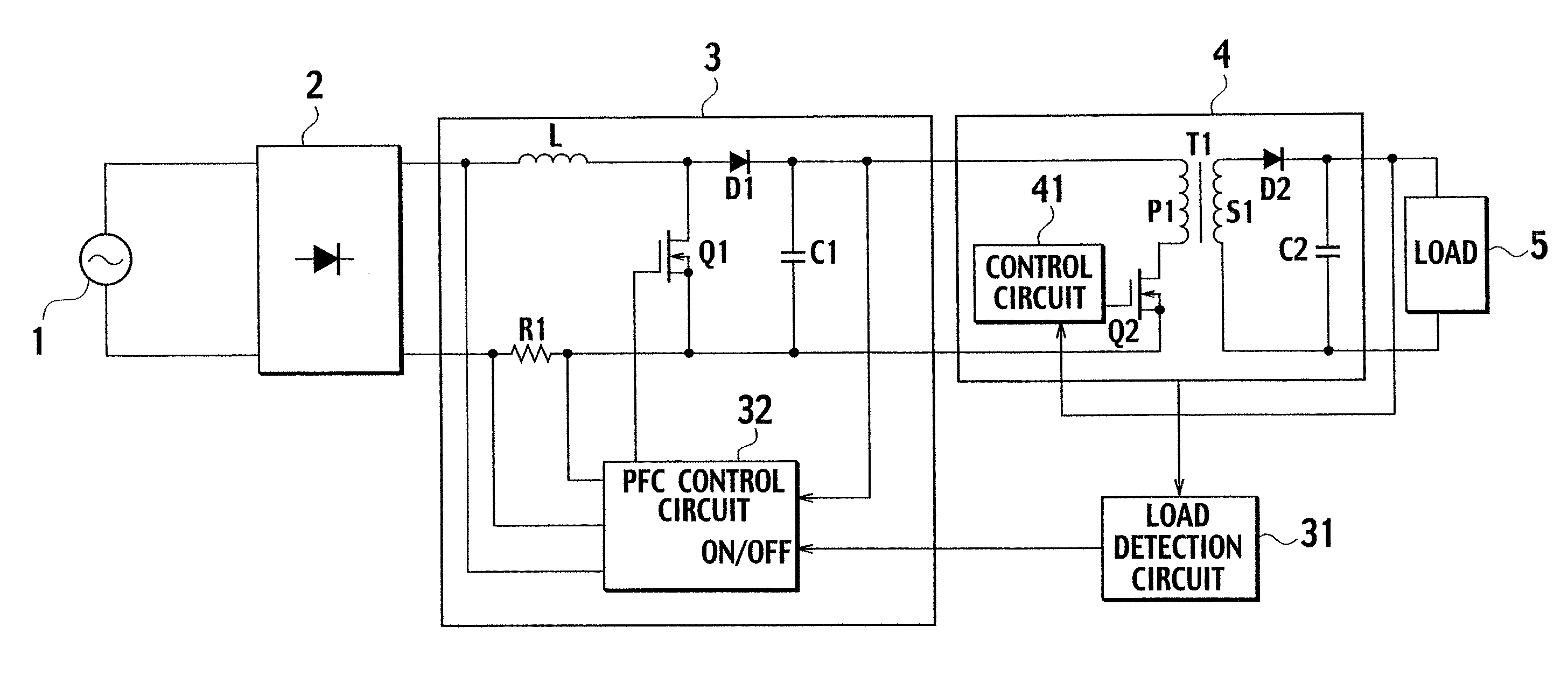
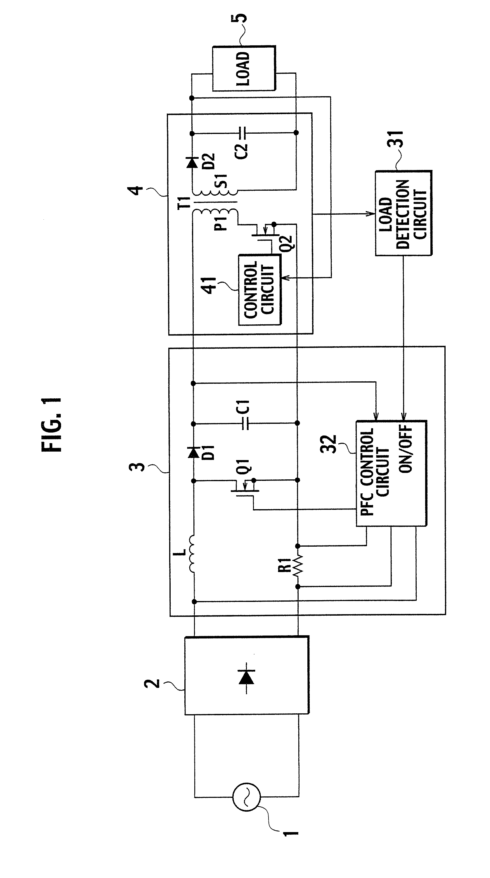
[0043]FIG. 5 is a circuit diagram of a switching power supply device according to a first embodiment of the present invention. In the switching power supply device shown in FIG. 5, the rectifier 2 rectifies an AC input voltage supplied from the AC power supply 1, and outputs the voltage to a PFC circuit 3a. The PFC circuit 3a converts from AC as pulsating wave into DC, and shapes a waveform of the input current rectified in the rectifier 2 so that a waveform of the input current is proportional to that of the input voltage, thereby correcting a power factor and suppressing harmonic components in a current.

[0044] A DC-DC converter 4a converts an output voltage of the PFC circuit 3a into a predetermined voltage to be fed to the load 5. The load detection circuit 31 detects power consumption by the external load 5 of the DC-DC converter 4a. A PFC on-off circuit (power conversion controller) 34 provides an ON signal or an OFF signal to the PFC control circuit 32a so as to enable the PF...

second embodiment

[0061]FIG. 9 is a circuit diagram of a switching power supply device according to a second embodiment of the present invention. In the switching power supply device of the second embodiment, an input terminal of the output voltage controller 33 and that of the PFC on-off circuit 34 are connected to output terminals of the rectifier 2 via an AC-DC converting circuit 35, thereby directly detecting the AC input voltage Vac. The AC-DC converting circuit 35 comprises a diode D11 and a capacitor C11. The output voltage controller 33 and the PFC on-off circuit 34 form an input voltage detection circuit. A DC voltage that is outputted via the AC-DC converting circuit 35 and that is proportional to the AC input voltage Vac is referred to as an AC input voltage Vac′ below.

[0062] In the present embodiment, the input voltages to the output voltage controller 33 and to the PFC on-off circuit 34 increase as the AC input voltage Vac increases, and the input voltages to the output voltage controll...

third embodiment

[0070]FIG. 12 is a circuit diagram of a switching power supply device according to a third embodiment of the present invention. In the switching power supply device of the third embodiment shown in FIG. 12, the AC input voltage Vac′ outputted from the rectifier 2 is supplied to the input terminal of the output voltage controller 33, and an output voltage of the PFC circuit (the voltage across the capacitor C1), which varies depending on the AC input voltage Vac, is fed to the input terminal of the PFC on-off circuit 34a.

[0071] Since the output voltage controller 33 and the PFC on-off circuit 34a are identical with those of the second embodiment, operations of the third embodiment are similar with those of second embodiment. Accordingly, similar effects with those of the second embodiment are obtained.


PUM


Abstract

A switching power supply device has a boost power converter which converts a wide range of AC input voltages into a DC voltage larger than an amplitude of the AC input voltage to supply to a DC-DC converter. The switching power supply device includes a load detection circuit, an input voltage detection circuit, and a power conversion controller for the boost power converter. The power conversion controller corrects the determination reference value in accordance with the AC input voltage detected in the input voltage detection circuit. When a light load is detected based on a comparison between the corrected determination reference value and the detection value output from the load detection circuit, the controller disables the boost power converter.

Description

BACKGROUND OF THE INVENTION [0001] The present invention relates to a switching power supply device that includes a boost power converter capable of correcting a power factor. More particularly, the invention relates to an active power-factor correction device (PFC device) circuit capable of correcting a power factor in response to power consumption in an external load. [0002] In response to the global trend of energy savings, efforts to use energy more efficiently have been expended. To save energy, the IEC (the International Electrotechnical Commission) has defined a series of standards for power supply devices for use in electric appliances or equipment. The standards include the IEC-1000s related to harmonic components in a current in a power supply device. In addition, the environmental protection agency's (EPA's) specifications, the so-called ENERGY STAR, require to attain average power conversion efficiency of 84% or greater at each of output load factors of 25%, 50%, 75%, an...

Claims


Application Information

Patent Timeline
Patent Type & Authority Applications(United States)
IPC IPC(8): G05F1/70
CPCH02M1/36H02M1/4225H02M2001/0032Y02B70/126Y02B70/16Y02B70/10H02M1/0032
Inventor TAKEUCHI, TOSHIROU
Owner SANKEN ELECTRIC CO LTD
Why Eureka
Try Eureka