

Polymer solar cell and method of manufacturing the same
a technology solar cells, applied in the field of polymer solar cells, can solve the problems of high manufacturing cost, inability to apply to flexible substrates, and inability to meet the needs of practical use, and achieve the effect of high power conversion efficiency
- Summary
- Abstract
- Description
- Claims
- Application Information
AI Technical Summary
Benefits of technology
Problems solved by technology
Method used
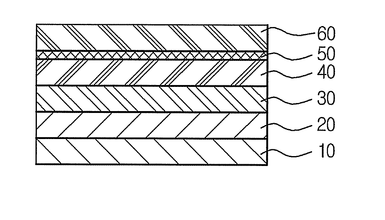
Image

Examples
example 1
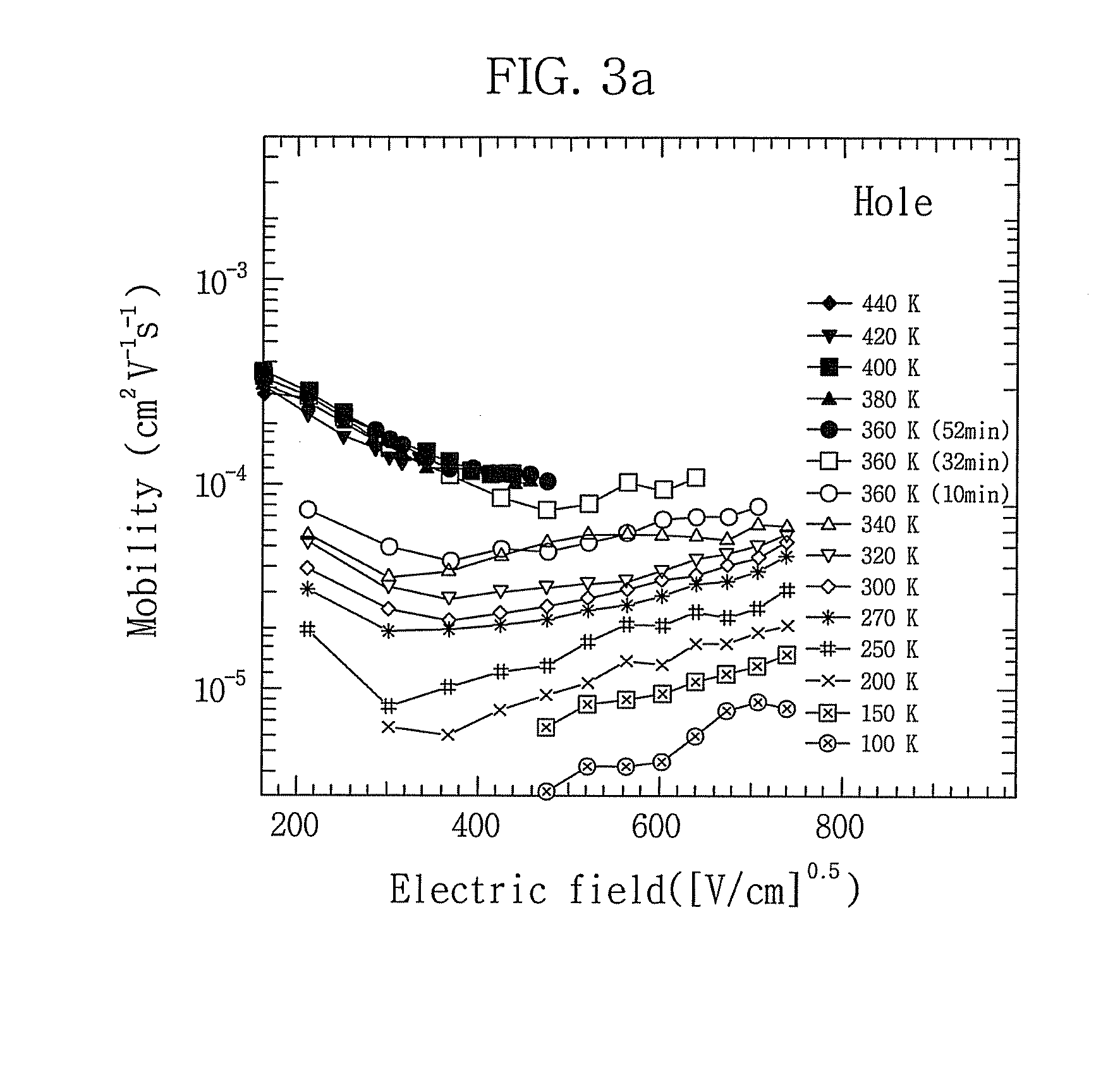
Measurement of Charge Mobility of P3HT:PCBM Blend Layer
(1) Fabrication of Measurement Device
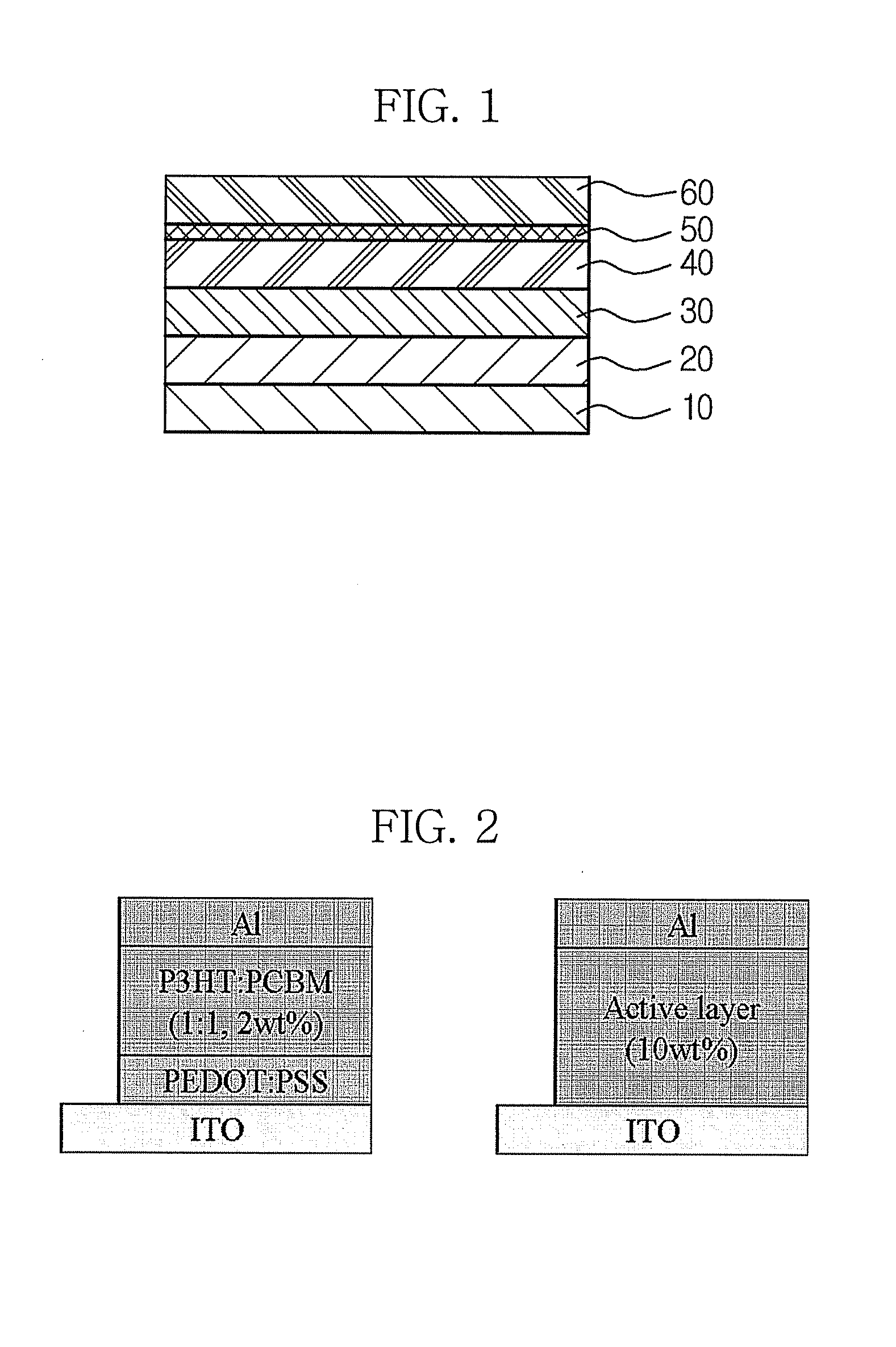
[0058]PEDOT:PSS [Baytron P AI 4083 poly(3,4-ethylenedioxythiophene) / poly(styrenesulfonate)] was applied on dry ITO glass through spin coating at 4000 rpm for 30 seconds (sec.). The coated device was dried in a vacuum oven at 120° C. for 30 minutes (min) or longer. A P3HT:PCBM blend solution was applied onto the substrate coated with the PEDOT:PSS film via spin coating at 1000 rpm for 30 sec.
[0059]The P3HT:PCBM blend solution was prepared as follows. P3HT and PCBM were separately dissolved to 4 weight percent (wt %) in a chlorobenzene solvent and then dispersed on a hot plate at 50° C. or higher for 30 min or longer using stirring magnets. The P3HT solution and the PCBM solution were filtered using a 0.3 micrometer (μm) PVDF filter, and a 0.5 μm PVDF filter, respectively. By adjusting the ratio of the individual P3HT and PCBM solutions, P3HT:PCBM blend solutions having various concentrations w...
example
(2)
Fabrication of a Polymer Solar Cell
Comparative Example 1
[0065]A glass substrate coated with ITO was dipped in distilled water, in which a detergent was dissolved, and was then subjected to ultrasonic cleaning for 30 min. Subsequently, the glass substrate was dipped in distilled water, subjected to ultrasonic cleaning for 5 min, and then the washing was repeated twice more.
[0066]After the completion of the distilled water washing, the glass substrate was subjected to ultrasonic cleaning in the solvents isopropyl alcohol, acetone, and methanol, in that order, and was then dried. The glass substrate coated with ITO was subjected to plasma treatment for 5 min under the conditions of 14 mtorr pressure and 50 W power, using nitrogen plasma in a plasma cleaner.
[0067]On the ITO transparent electrode, 1 ml of a PEDOT:PSS solution (Baytron P AL 4083, available from Bayer), mixed 1:1 in chlorobenzene, was spin coated at 4,000 rpm for 30 sec. This process formed a hole injection layer 200 nm...
PUM
| Property | Measurement | Unit |
|---|---|---|
| thickness | aaaaa | aaaaa |
| thickness | aaaaa | aaaaa |
| area | aaaaa | aaaaa |
Abstract
Description
Claims
Application Information