Clamp for processing glass mould

A technology of glass molds and fixtures, which is applied in metal processing, metal processing equipment, metal processing machinery parts, etc., can solve the problems of lack, difficulty in obtaining levelness of glass mold half molds, etc., and achieve the effect of ensuring processing quality

Active Publication Date: 2012-11-21
CHANGSHU JIANHUA MOLD TECH
View PDF4 Cites 51 Cited by
  • Summary
  • Abstract
  • Description
  • Claims
  • Application Information

AI Technical Summary

Problems solved by technology

[0006] However, the above-mentioned structure still has shortcomings in the actual use process, due to the longitudinal direction of the glass mold half mold held between the first and second clamps The middle and lower parts are in a suspended state, that is to say, the middle and lower parts of the outer circular surfaces on both sides of the length direction of the glass mold half-mold lack the necessary support, so the first and second mold level adjustment mechanisms act on a pair of joints at the same time. surface, it is very likely that it is difficult to obtain the overall levelness of the glass mold half-mold, especially when the first and second mold level adjustment mechanisms leave the joint surface, and in the process of machining the joint surface or mold cavity by the CNC machine tool In the process, the horizontality of the glass mold half changes, and even the sinking phenomenon occurs. The so-called sinking phenomenon refers to the glass mold half breaking away from the first and second clamps and falling

Method used


Image

  • Clamp for processing glass mould
  • Clamp for processing glass mould
  • Clamp for processing glass mould

Examples


Embodiment Construction

[0023] In order to enable the examiners of the patent office, especially the public, to understand the technical essence and beneficial effects of the present invention more clearly, the applicant will describe in detail the following in the form of examples, but none of the descriptions to the examples is an explanation of the solutions of the present invention. Any equivalent transformation made according to the concept of the present invention which is merely formal but not substantive shall be regarded as the scope of the technical solution of the present invention.

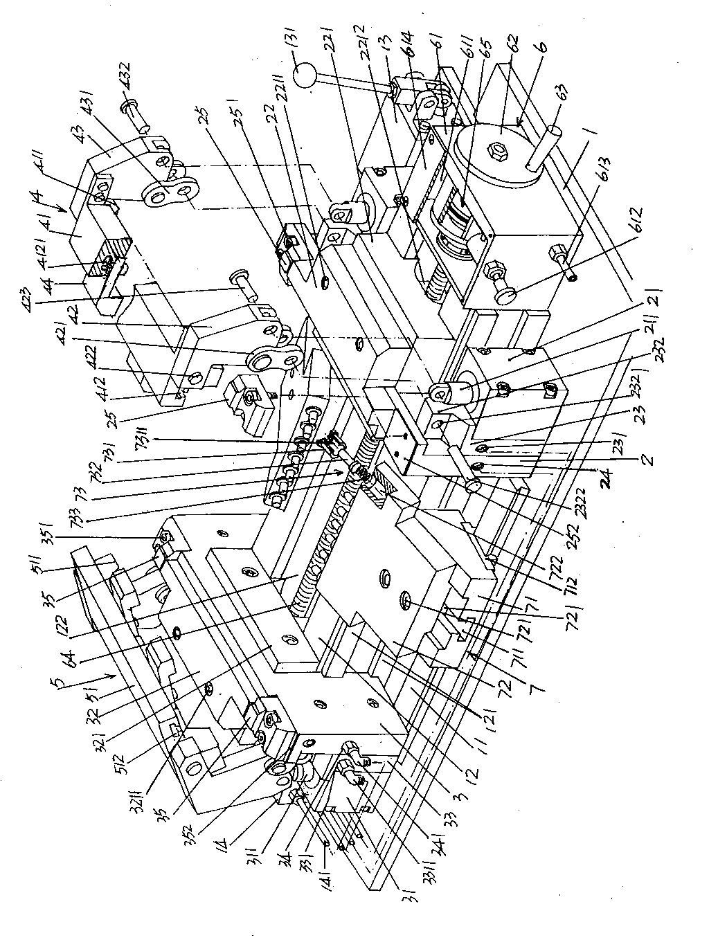
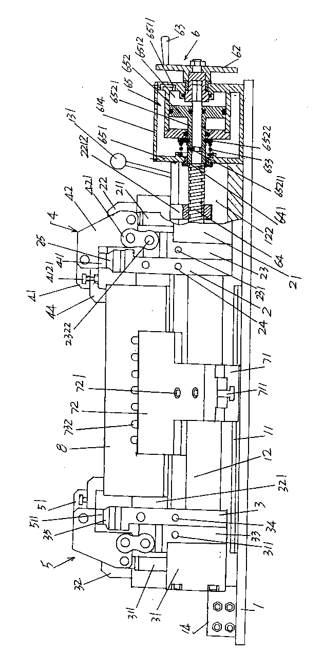
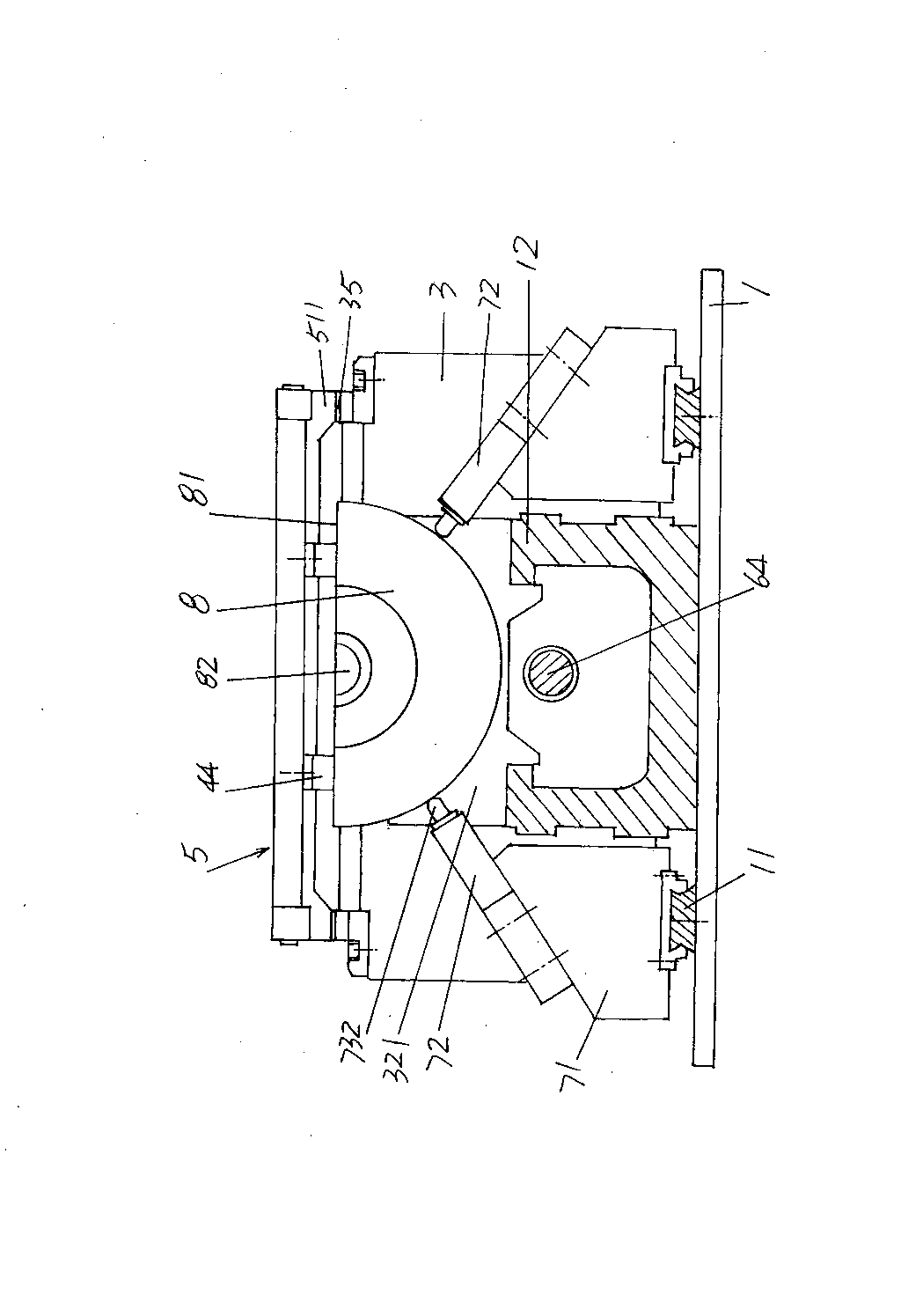
[0024] Please see figure 1 and figure 2 , in the figure 1 and figure 2 Provides a base 1 that is generally rectangular parallelepiped, and the base 1 is fixed on a numerically controlled machine tool or similar equipment during use. Depend on figure 1 As shown, a guide rail bar 11 is formed on the longitudinal direction of the base 1, that is, both sides of the longitudinal direction and on th...


PUM


Abstract

The invention discloses a clamp for processing a glass mould, and belongs to the technical field of tooling clamps. The clamp comprises a base, a first clamp platform fixed mount, a second clamp platform fixed mount, a first mould horizontal adjusting mechanism, a second horizontal adjusting mechanism and a clamp platform driving mechanism, wherein a pair of guide rail bars is arranged on two sides of the base respectively, a clamp platform fixed mount sliding seat is arranged between the guide rail bars, and guide rails and a clamp platform moving chamber are formed on the clamp platform fixed mount sliding seat; the first clamp platform fixed mount and the second clamp platform fixed mount are positioned on the base respectively, a first acting cylinder and a second acting cylinder are fixed at two ends of the first clamp platform fixed mount and the second clamp platform fixed mount respectively, and a first clamp platform fixed seat and a second clamp platform fixed seat are fixedin the middle parts of the first clamp platform fixed mount and the second clamp platform fixed mount respectively; the first mould horizontal adjusting mechanism and the second mould horizontal adjusting mechanism are arranged on the first clamp platform fixed mount and the second clamp platform fixed mount respectively; and the clamp platform driving mechanism is arranged on the base. The clampis characterized by also comprising a pair of horizontal supporting adjusting mechanisms which are arranged on a pair of guide rail bars respectively, wherein each horizontal supporting adjusting mechanism comprises an adjusting base, an adjusting top plate and a group of elastic stretching devices. The clamp has the advantage that a half-mould of the glass mould cannot fall off to ensure the processing quality.

Description

technical field [0001] The invention belongs to the technical field of fixtures, and in particular relates to a fixture for glass mold processing. Background technique [0002] Fixtures play a very important role in the production of industrial products, and the production of glass molds is no exception. The so-called tooling mold refers to special equipment or tools used to clamp or position workpieces in machining to meet certain process requirements. Fixtures usually need to meet the requirements of no interference during product production, accurate and reliable positioning, and convenient operation. Since the tooling fixture has the exclusive characteristics of manufacturing a certain product, the degree of generalization is low, and it is often made by the manufacturer of mechanical products. Glass mold manufacturers also mostly equip various tooling fixtures in a self-made way. In recent years, although all kinds of medium and high-end machining centers (comprehensi...

Claims


Application Information

Patent Timeline
Patent Type & Authority Patents(China)
IPC IPC(8): B23Q3/08B23Q7/00
Inventor 马建华晏庆宝朱伟国沈军韩志强
Owner CHANGSHU JIANHUA MOLD TECH
Why Eureka
Try Eureka