Overhanging sensor support

A sensor bracket and sensor technology, applied in the direction of instruments, measuring instrument components, measuring devices, etc., can solve the problems of not being able to adapt to the natural change of the fit clearance, enlarging the fit clearance of the pin shaft, increasing the influence of the fit clearance, etc.

Inactive Publication Date: 2015-04-29
济南数锐电子科技有限公司
View PDF7 Cites 0 Cited by
  • Summary
  • Abstract
  • Description
  • Claims
  • Application Information

AI Technical Summary

Problems solved by technology

[0006] When the sensor bracket is unfolded, it will form an overhang structure supported only by the pin shaft, or there is only one support point. Mechanically, as long as it is a movable fit, there must be a fit gap, and the overhang end will enlarge the pin shaft. Fit the gap, and the longer the bracket, the greater the sag of the overhanging end, which cannot ensure that the sensors in the linear array are on the same level
And as the service life increases, the fit clearance will gradually increase
[0007] In view of this, currently, for example, the

Method used


Image

  • Overhanging sensor support
  • Overhanging sensor support
  • Overhanging sensor support

Examples


Embodiment Construction

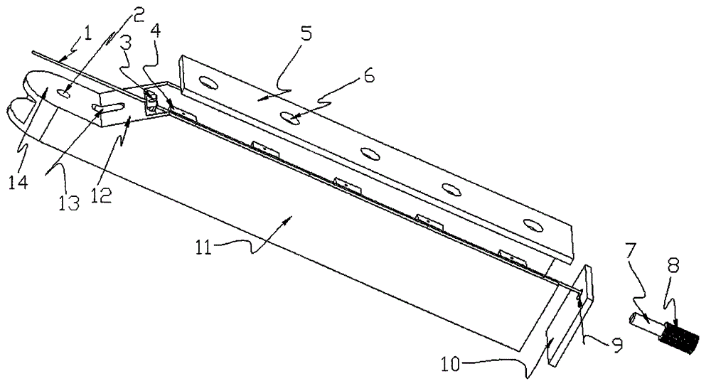
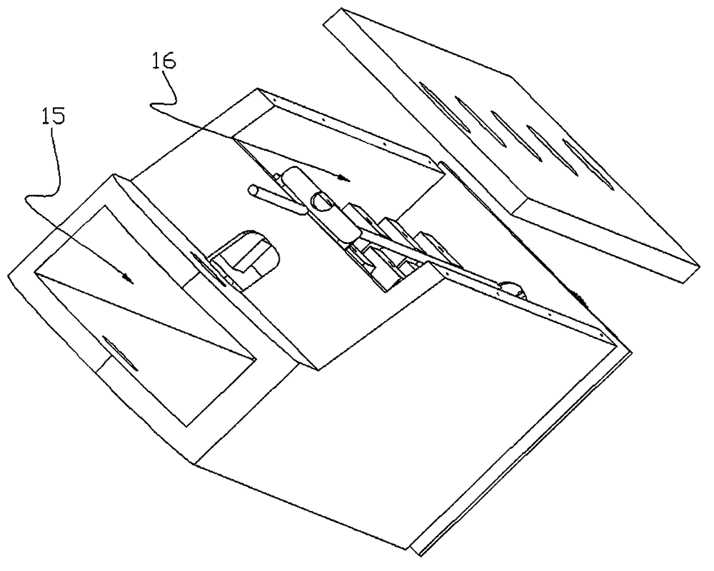
[0039] Overhang sensor brackets are generally foldable to facilitate transportation or storage. This kind of overhang sensor bracket usually has two states, one is the folded state, and the other is the overhang state. The overhang direction mentioned in the present invention refers to the overhang direction in the overhang state. The technical staff can understand.

[0040] The overhang, as described in the background art, usually one end is mounted on the machine body through a pin to form a swing rod, and then a controllable unfolded state, or overhang state, is formed by certain constraints.

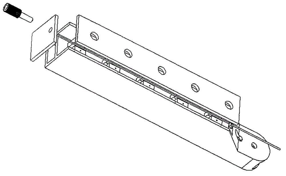
[0041] Force analysis: For the overhang, when the suspension point of the steel cable 1 is higher than the middle position of the overhang in the vertical direction, and the other end of the steel cable 1 is also higher than the middle position, pull the steel cable 1, An upward force will be applied to the overhanging end of the overhang.

[0042] Cooperate with the level gauge, make the...


PUM


Abstract

The invention discloses an overhanging sensor support. The overhanging sensor support comprises a base part and an overhanging part used for linearly arraying sensors, wherein one end of the overhanging part is installed on the base part through a vertical pin shaft, so that the overhanging part has a freedom degree of rotating around the axis of the pin shaft. A first rope hanging part is arranged on the upper portion of the base part, and correspondingly a second rope hanging part is arranged on the upper portion of the other end of the overhanging part. The overhanging sensor support is further provided with a steel rope connected with the first rope hanging part and the second rope hanging part, and the first rope hanging part or the second rope hanging part is a movable rope hanging part of which the position can be adjusted in the connecting line direction of the first rope hanging part and the second rope hanging part. A level gauge is arranged on the upper surface of the overhanging part. The overhanging sensor support can be in an ideal level state when unfolded.

Description

Technical field [0001] The invention relates to a cantilever bracket for arranging sensors. Background technique [0002] In some applications, the use of sensors is not the use of a single sensor, but requires multiple sensors to form a specific array, so that accurate sampling can be obtained. It can be seen that the sampling accuracy is not only related to the accuracy of the sensor itself, but also related to the array. The array inevitably needs to be supported by a predetermined layout to form a support for the sensor. [0003] In some applications, the shape of the array needs to be stable. For example, it is necessary to strictly control that all sensors are located on the same plane, and the distance between the sensors remains unchanged. This requires the support to have a certain degree of stiffness, more often static stiffness. [0004] In practical applications, those skilled in the art will inevitably face such situations. For example, the sensor holder has a foldabl...

Claims


Application Information

Patent Timeline
IPC IPC(8): G01D11/30
Inventor 王世建车伟
Owner 济南数锐电子科技有限公司
Why Eureka
Try Eureka