Spiral heat accumulating type gas electronic waste pyrolysis system

An electronic waste, regenerative technology, applied in special forms of dry distillation, indirect heating dry distillation, petroleum industry and other directions, can solve the problems of accelerating the pyrolysis speed of electronic waste, reducing the service life of coal plates, affecting the working process, etc. Sexual interspersed, increased intensity, and the effect of speeding up the work process

Inactive Publication Date: 2020-12-08
黄菊青
View PDF0 Cites 1 Cited by
  • Summary
  • Abstract
  • Description
  • Claims
  • Application Information

AI Technical Summary

Problems solved by technology

[0003] In view of the above, once it is used for a long time, under the condition of concentrated heating, the four sides will have different degrees of downward deflection deformation, and the middle part will inevitably produce an upward arching phenomenon, so that the contact between the coal plate and the front end of the card slot changes from surface contact to line contact. , which greatly reduces the service life of the coal slab, seriously affects the working process of the next process, and due to the deformation of the coal slab, it cannot continue to maintain the ideal horizontal state, and the briquettes roll down and accumulate on the four sides along the deformation inclination angle, resulting in the accumulation of briquettes inside Insufficient oxygen interferes with the complete combustion of briquettes and cannot effectively accelerate the pyrolysis speed of electronic waste. The present invention provides a spiral regenerative gas-fired electronic waste pyrolysis system

Method used


Image

  • Spiral heat accumulating type gas electronic waste pyrolysis system
  • Spiral heat accumulating type gas electronic waste pyrolysis system
  • Spiral heat accumulating type gas electronic waste pyrolysis system

Examples


Embodiment 1

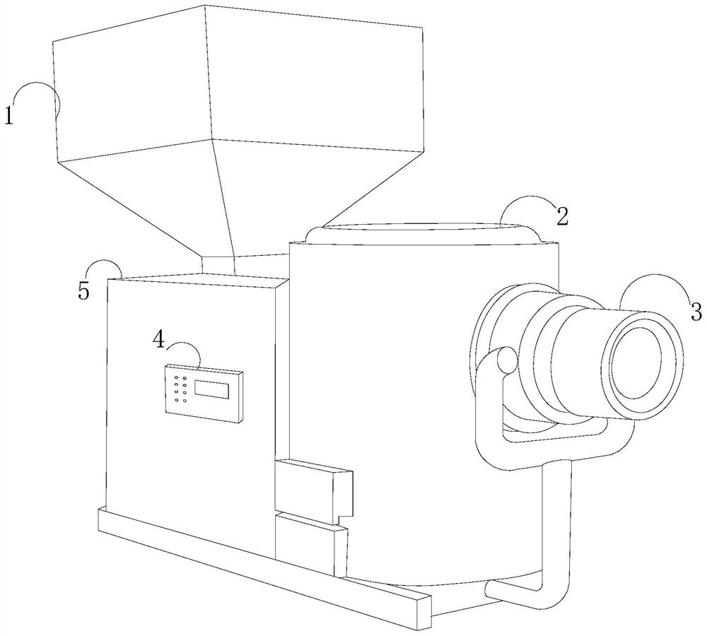
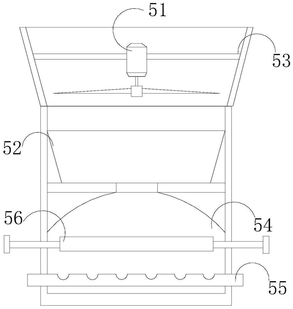
[0030] such as Figure 1- Figure 4 As shown, the invention provides a spiral heat storage type gas electronic waste pyrolysis system, which comprises a feed funnel 1, a reaction chamber 2, a discharge pipe 3, a control key 4, and a combustion chamber 5, wherein the feed funnel 1 is fixedly connected to the top of the combustion chamber 5, and the interior of the combustion chamber 5 is communicated with each other; the control key 4 is installed on the outer surface of the combustion chamber 5, and is electrically connected with the reaction chamber 2 through the combustion chamber 5; and the bottom conduit end of the reaction chamber 2 extends to the receiving port of the discharge pipe 3. The combustion chamber 5 comprises a radiating fan 51, a pyrolysis regulating pot 52, a partition 53, a heat storage port 54, an aeration ring 55 and a deformation tool 56. The middle of the partition 53 is provided with the radiating fan 51, and the bottom fan of the radiating fan 51 is aligned...

Embodiment 2

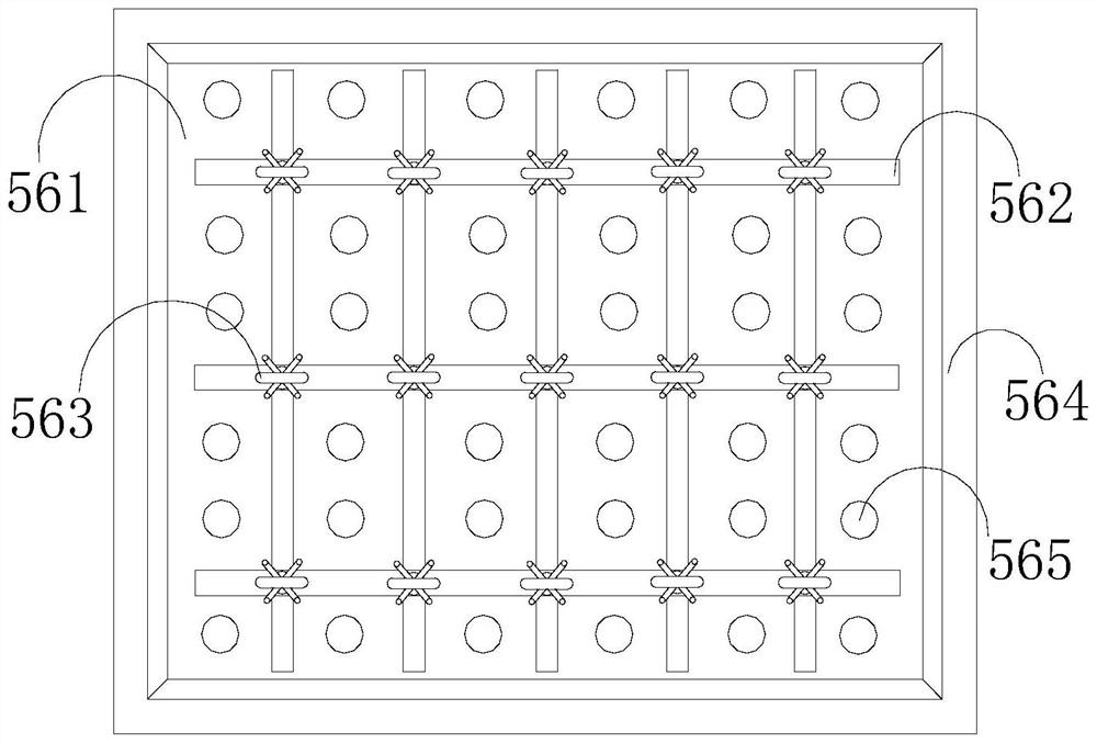
[0032] such as Figure 5- Figure 7 As shown, on the basis of Embodiment 1, the present invention combines the cooperation of the following structural components, and the sliding swing groove 634 includes a guide rail channel 341, an alignment support plate 342, and an end sleeve holder 343. Two end sleeve holders 343 with the same structure are embedded and fixed in the guide rail channel 341, and two alignment support plates 342 with the same structure are installed at their ports, and the end sleeve holders 343 are buckled with the clamping ends of the arc-shaped clamping posts 636. The clamping device 631 comprises a sleeve member 1a1, an accommodating socket 1a2, a running-in layer 1a3, a pressure-bearing structure 1a4, a tip contact angle 1a5 and a sliding groove 1a6, wherein the top of the sleeve member 1a1 is welded and connected with the tip contact angle 1a5 movably crossing the bottom of the frame 562, and grooves with sliding grooves 1a6 on both sides are movably engaged...


PUM


Abstract

The invention discloses a spiral heat accumulating type gas electronic waste pyrolysis system which structurally comprises a feeding funnel, a reaction chamber, a discharging pipe, a control key and acombustion chamber; the feeding funnel is fixedly connected to the top of the combustion chamber and internally communicated with the combustion chamber; the control key is installed on the outer surface of the combustion chamber and electrically connected with the reaction chamber through the combustion chamber; and the guide pipe end at the bottom of the reaction chamber extends to a receivingopening of the discharging pipe. Vertical fluctuation of the whole deformation tool in different degrees is borne through cooperation between a frame and a swing supporting device; the frame is composed of two or more rectangular grids, and sufficient deformation allowance is provided for heating deformation of the coal supporting plate in the normal heating process; and the strength of the coal supporting plate is improved structurally, and surface contact between the coal supporting plate and the foremost end of the clamping groove is prevented from being changed into line contact.

Description

Technical field [0001] The invention relates to the field of garbage disposal, in particular to a spiral heat storage type gas electronic garbage pyrolysis system. technical background [0002] The existing electronic waste pyrolysis system is provided with a coal plate, because when the coal plate is burning coal, its lower part is generally hollow, and its four sides are placed in the clamping groove, and the coal plate and the clamping groove are kept in a closed state of coaxial alignment, which is convenient for air circulation and users to place the number of small coal balls according to the amount of garbage. As the small coal balls are added, the pyrolysis speed of electronic waste is effectively accelerated. Once used for a long time, under the condition of centralized heating, Its four sides will bend down in different degrees, and the middle part will inevitably arch up, which makes the contact between the coal board and the front end of the clamping groove change fro...

Claims


Application Information

Patent Timeline
Patent Type & Authority Applications(China)
IPC IPC(8): C10B53/00C10B47/00B09B3/00
CPCB09B3/00C10B47/00C10B53/00
Inventor 黄菊青
Owner 黄菊青
Why Eureka
Try Eureka