Nozzle of bladeless fan

A technology of fans and nozzles, applied in the field of nozzles of bladeless fans, can solve problems such as limited influence range

Inactive Publication Date: 2012-03-07
王宁雷
View PDF4 Cites 98 Cited by
  • Summary
  • Abstract
  • Description
  • Claims
  • Application Information

AI Technical Summary

Problems solved by technology

The range that the wind can affect is limited. When some people are many and scattered, when there are people on both sides of the fan, it cannot meet the demand.

Method used


Image

  • Nozzle of bladeless fan
  • Nozzle of bladeless fan
  • Nozzle of bladeless fan

Examples


Embodiment 1

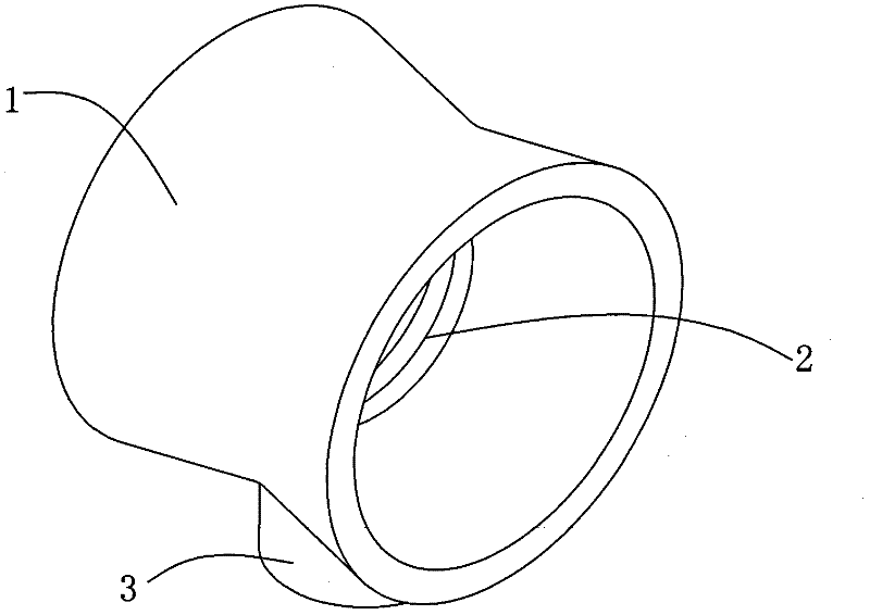
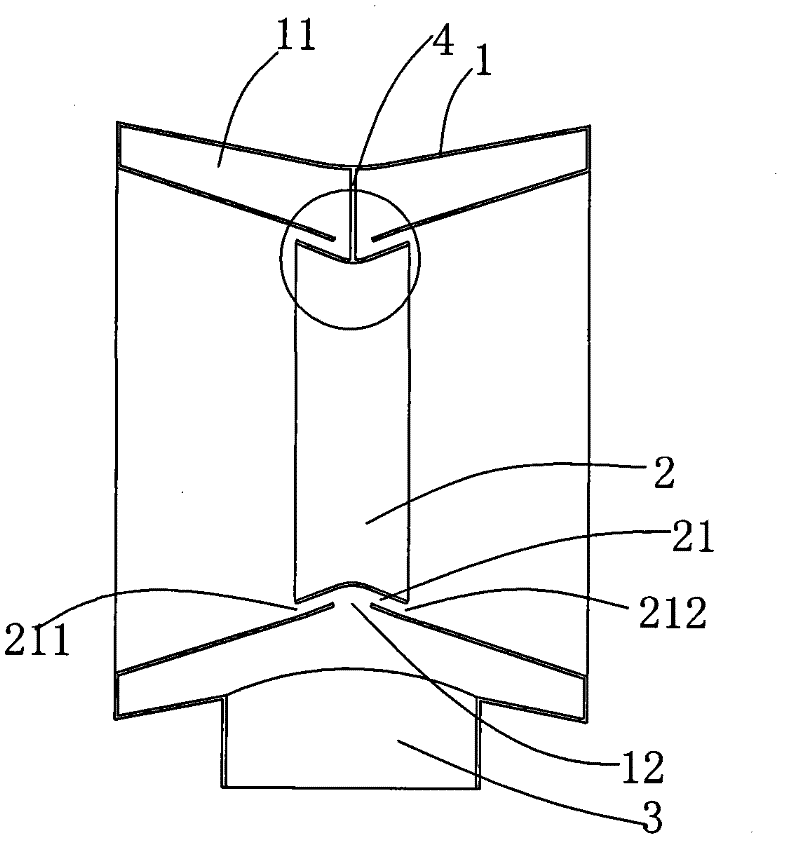
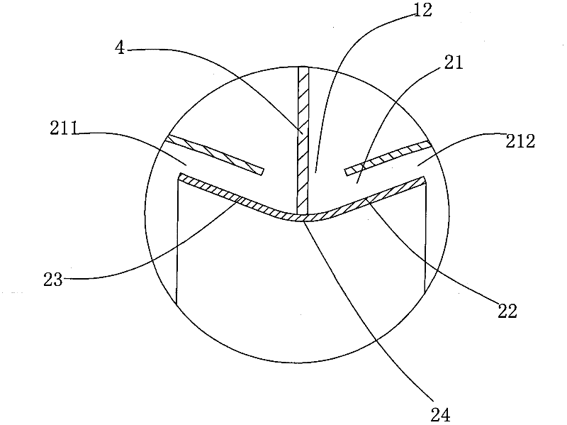
[0015] Example 1, see Figure 1 to Figure 3 , a bladeless fan nozzle, including a ring-shaped casing 1, a ring-shaped deflector 2 and a connecting piece 4, the inside of the casing 1 is formed with an air inlet channel 11, and the lower part of the casing 1 is provided with a The channel 11 communicates with the opening 12 . The inner circle of the housing 1 has the smallest diameter at the two ends of the opening 12 and gradually increases towards the two ends of the housing 1, forming a "V" shape. The middle part of the inner ring of the housing 1 is formed with a ring-shaped opening 12 communicating with the air inlet channel 11. The deflector 2 is located in the inner ring of the housing 1, and the outer ring of the deflector 2 is connected to the inner ring of the housing 1. An air outlet channel 21 with two opposite air outlets 211 , 212 is formed between them, and the opening 12 communicates with the air outlet channel 21 and the air inlet channel 11 . The outer ring ...

Embodiment 2

[0017] Example 2, see Figure 4 , this embodiment uses the plate as the connector 4 to realize the connection between the deflector 2 and the housing 1, the two ends of the plate are respectively fixed to the inner ring of the housing 1 and the circular table surface 22, 23, and the rest are of the same structure Embodiment 1 will not be repeated here. In this connection mode, both ends of the deflector 2 are fixed, and the connection of the deflector 2 is more reliable.

Embodiment 3

[0018] Example 3, see Figure 5 In this embodiment, bolts 51 and nuts 52 are used to realize the connection between the deflector 2 and the housing 1, and the bolt 51 is screwed to the nut 52 after passing through the housing 1 and the deflector 2, and the rest of the structure is the same as that of the embodiment 1. , which will not be repeated here. In this way, the deflector 2 can be disassembled by unscrewing the nut 52 .


PUM


Abstract

The invention discloses a nozzle of a bladeless fan, belonging to the technical field of fans. The nozzle comprises an annular shell and an annular flow guide plate; the shell is internally provided with an air intake channel; the shell is provide with an opening which is communicated with the air intake channel; the flow guide plate is positioned in the inner ring of the shell and is fixed on the shell; an air outlet and an air outlet channel which are arranged in opposite are formed between the outer ring of the flow guide plate and the inner ring of the shell; and the opening is communicated with the air outlet channel and an air inlet channel. After air flow is blown to the opening from the air inlet channel, the air flow enters the air outlet channel, and then is blown out of the two air outlets which are arranged in opposite, thus the air flow can be blown out of a positive surface and a negative surface of the nozzle simultaneously, and the nozzle is especially suitable for occasions when people are at the positive surface and the negative surface of the fan.

Description

technical field [0001] The invention belongs to the technical field of fans, and in particular relates to a nozzle of a bladeless fan. Background technique [0002] Bladeless fans generally blow air to one side. For example, patent application number: 200810177844.8 discloses a bladeless fan. The nozzle of this bladeless fan is a ring-shaped shell, and the inside of the shell is provided with an air inlet channel. , the casing is also provided with a ring of openings communicating with the channel. When in use, the air flows into the casing, enters the air inlet channel, and then blows out through the opening. The opening of such nozzles generally only faces one side. The range that the wind can affect is limited. When there are many and scattered people, it cannot meet the demand when there are people on both sides of the fan. Contents of the invention [0003] Aiming at the deficiencies in the prior art, the present invention provides a nozzle of a bladeless fan, capab...

Claims


Application Information

Patent Timeline
Patent Type & Authority Applications(China)
IPC IPC(8): F04F5/44
CPCF04D25/08F04F5/16F04F5/46
Inventor 王宁雷
Owner 王宁雷
Why Eureka
Try Eureka