Internal combustion engine with an exhaust gas turbocharger

a technology of internal combustion engine and turbocharger, which is applied in the direction of machines/engines, mechanical equipment, and non-fuel substance addition to fuel, etc., can solve the problems of increasing the geometrical scale of the turbine of the exhaust gas turbocharger, the inability to meet the needs of the lower load and speed region of the internal combustion engine, and the inability to achieve optimal service. optimal, the effect of increasing the operating area

Inactive Publication Date: 2011-03-24
DAIMLER AG
View PDF16 Cites 52 Cited by
  • Summary
  • Abstract
  • Description
  • Claims
  • Application Information

AI Technical Summary

Benefits of technology

[0007]An internal combustion engine which enables an efficiency improvement in a larger operating region while maintaining cost-efficient production methods is created according to the invention in that the turbine of the exhaust gas turbocharger comprises an adjustment device by means of which a inlet cross section to the spiral channel and a nozzle flow cross section of the spiral channel leading to the receiving chamber of the turbine rotor can be adjusted together. In this manner, the aim of maintaining a cost-efficient production method, e.g. a sand casting method can be fulfilled on the one hand with low demands on the manufacture tolerances for the manufacture of the turbine housing and on the other hand a constructively particularly simple and variable adjustability of the gas supply to the turbine wheel with a corresponding efficiency increase of the exhaust gas turbocharger and thus of the internal combustion engine can be realized in a cost-effective manner. With the help of the adjustment device according to the invention, the back-pressure behavior of the turbine can be influenced in a defined manner and the gas supply to the turbine wheel can be controlled in a particularly simple manner between a partial and a full application. The internal combustion engine can in principle be a spark ignition, a self-ignition gasoline or a Diesel engine.
[0008]In a further advantageous arrangement of the invention it is provided that the adjustment device comprises an adjustment ring which is arranged concentrically with the axis of rotation of the turbine wheel disposed in the turbine housing and which is connected to at least one blocking body arranged in the region of the nozzle cross section. The blocking body is moved by rotational and / or translational movement of the adjustment ring at least between a position reducing the spiral inlet cross section and the nozzle cross section and a position increasing the spiral inlet cross section and the nozzle cross section. This represents a constructively simple and installation space saving possibility to influence the back-pressure forming capability of the turbine corresponding to the geometric design of the two cross sectional surfaces or of the blocking bodies to each other simultaneously by means of a simple rotary movement. Compared to the varied devices known from the state of the art, where guide vanes are rotated or displaced in an axial manner in front of the turbine wheel, there is additionally a large advantage with regard to a reduced mechanical susceptibility, or of the functional ensuring over the life of the internal combustion engine with low costs.
[0009]Advantageously, at least one blocking body is formed with an aerodynamic surface shape in its cross section. The inflow of the turbine wheel can be adapted hereby in a particularly simple manner to different geometric designs and aerodynamic properties of the turbine housing, whereby a further improvement of the overall efficiency of the internal combustion engine is provided.

Problems solved by technology

Thus, increasing demands regarding the charge pressure provision with high exhaust gas return rates over average to high load demand regions of the internal combustion engine result, whereby the turbines of exhaust gas turbochargers are increasingly scaled down geometrically.
These exhaust gas aftertreatment systems lead to a pressure increase at an exhaust gas outlet of the exhaust gas turbocharger.
With the design boundary conditions of exhaust gas turbochargers, which are usually defined by the nominal operating point, the charging change side and the usage side of the internal combustion engine, in particular the lower load and speed region of internal combustion engines can however not be served optimally even by exhaust gas turbochargers with two asymmetric spiral channels.
With the cost-efficient sand casting methods usually used for producing the turbine housing, there are additionally manufacture-technical limits, so that only spiral channels with nozzle cross sections over 4.5 mm can be reasonably accurately produced.
Thereby, comparatively high tolerances of 10% and more result with the casting, which leads to efficiency losses of the exhaust gas turbocharger.

Method used


Image

  • Internal combustion engine with an exhaust gas turbocharger
  • Internal combustion engine with an exhaust gas turbocharger
  • Internal combustion engine with an exhaust gas turbocharger

Examples


first embodiment

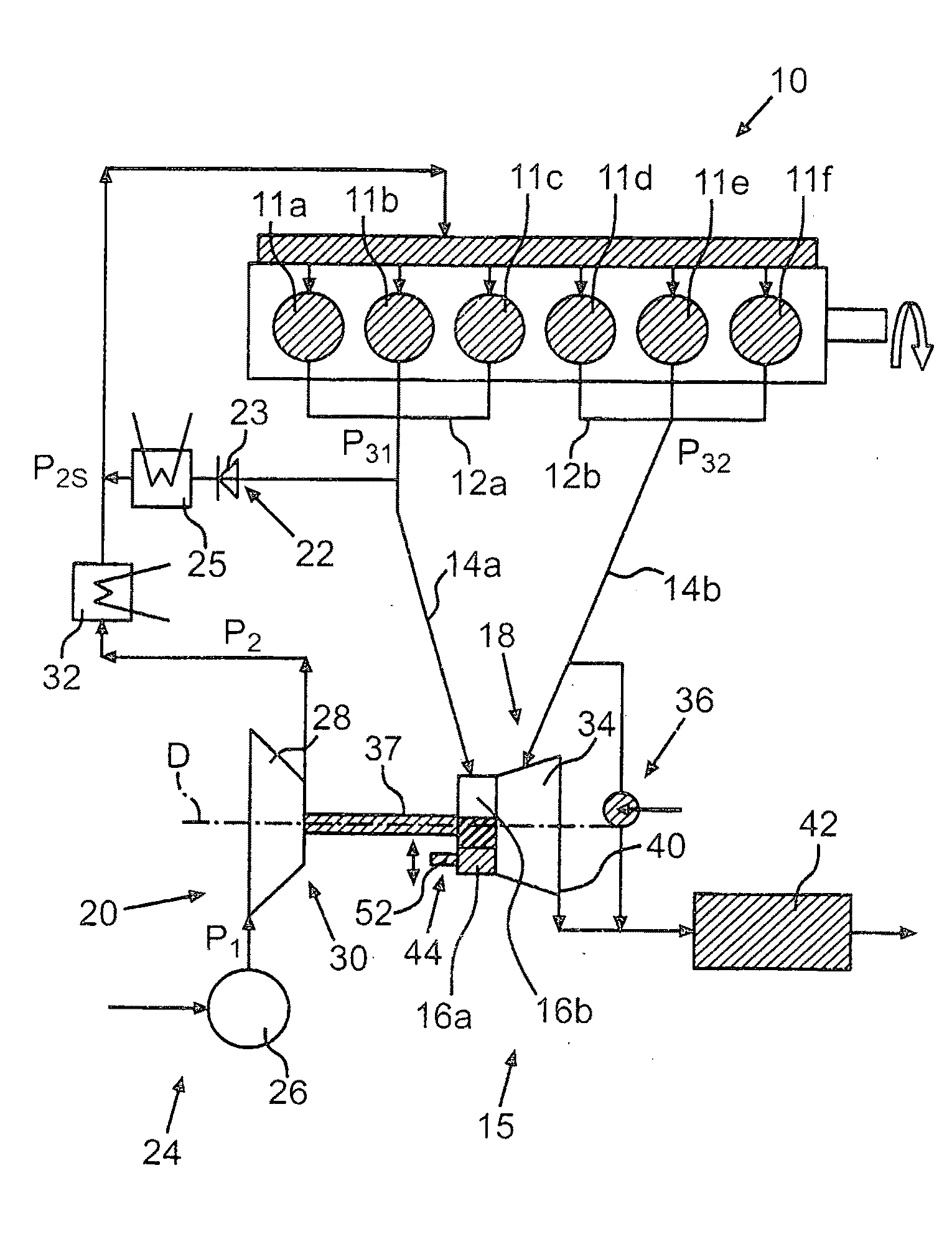
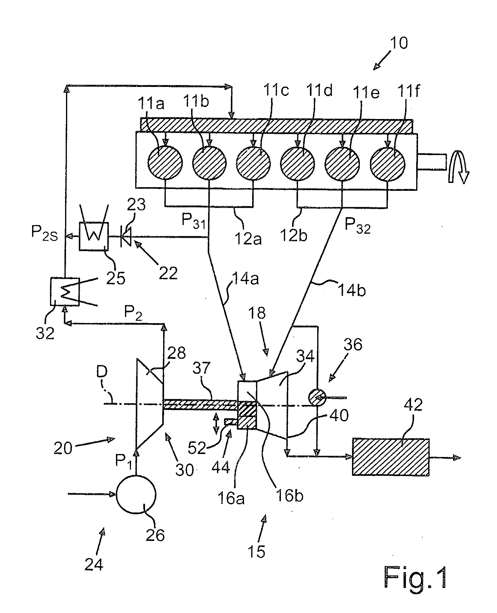
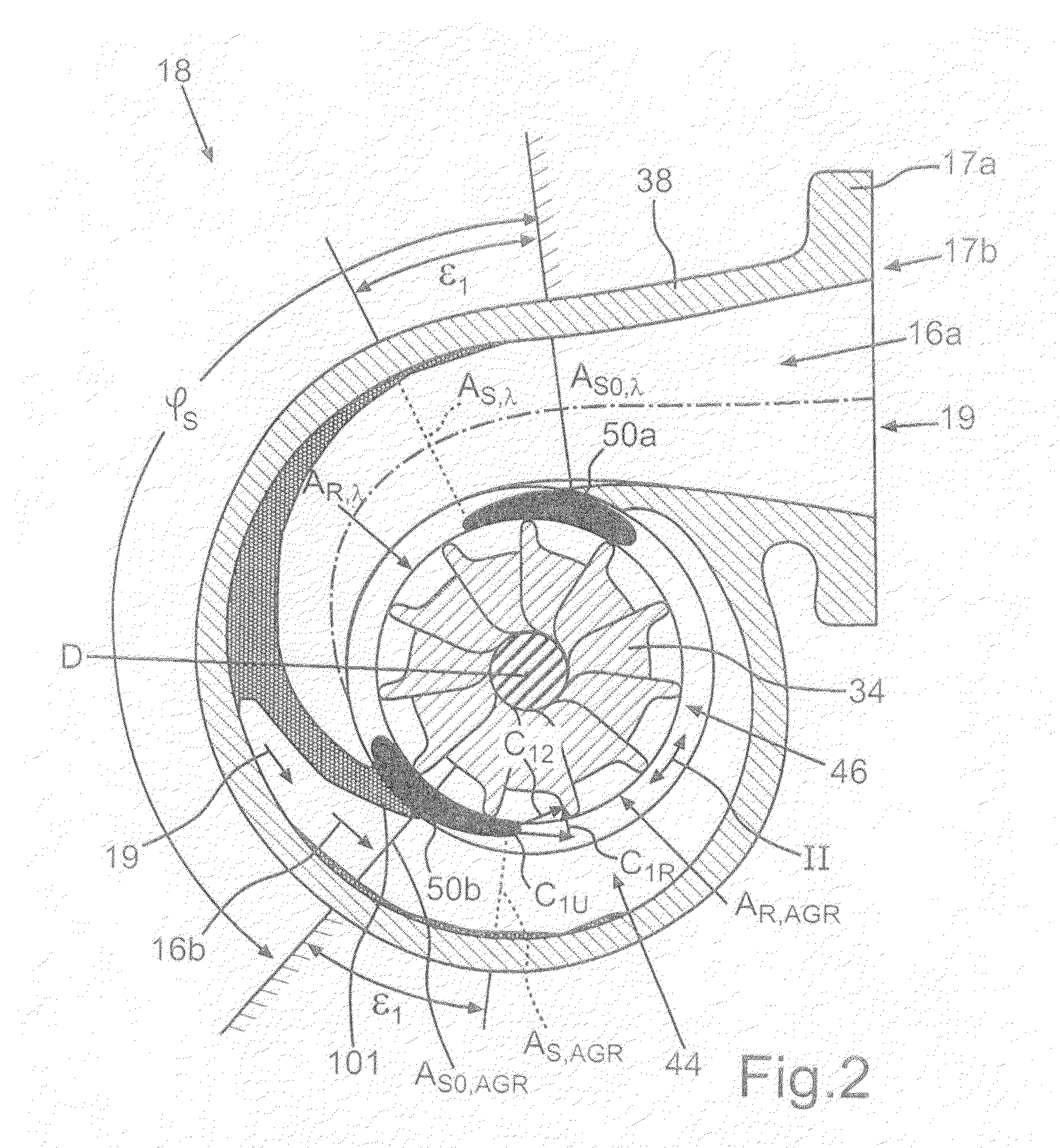
[0034]FIG. 1 shows in principle an internal combustion engine 10 for a commercial vehicle. The internal combustion engine 10 may be in principle a Diesel, a spark ignition or a compression ignition engine and as shown comprises 6 cylinders 11a-f of which the cylinders 11a-c are combined in a first cylinder group 12a and the cylinders 11d-f in a second cylinder group 12b. Two exhaust gas lines 14a, 14b of an exhaust gas tract 15 of the internal combustion engine 10 are associated with the cylinder groups 12a, 12b, of which the first exhaust gas line 14a is coupled to a first spiral channel 16a formed as a partial spiral via corresponding manifolds and the second exhaust gas line 14b to a second spiral channel 16b, also formed as a partial spiral of a turbine 18 of an exhaust gas turbo-charger 18. The spin-determining spiral channels 16a, 16b thereby comprise connection flanges 17a, 17b arranged adjacent to each other and sealed against each other in a gas-tight manner. The connectio...

third embodiment

[0043]FIG. 8 shows schematically of the internal combustion engine 10 in principle according to a Compared to the previous embodiments, the gas guiding device 36 is formed as a blow-by and blow-off device, so that the outlets of the three cylinders 11d-f can optionally be connected to one or several of the spiral channels 16b-d and / or exhaust gas can be guided past the turbine 18. The turbine 18 of the exhaust gas turbocharger 20 comprises the spiral channel 16a formed as an AGR spiral and connected to the exhaust gas line 14a, which—as described previously—is designed due to the AGR requirement as a partial spiral with the looping angle φS (see FIG. 4), which is chosen clearly below a full spiral of 360° due to the desired AGR capability (e.g. EPA07-limit value fulfillment) with an optimum design. The turbine 18 further comprises three further spiral channels 16b-d formed as λ-spiral segments with respective looping angles φ of about 120°, which are shown in FIG. 10 in more detail...


PUM


Abstract

In an internal combustion engine for a motor vehicle having an exhaust gas turbo-charger comprising a compressor arranged in an intake tract of the internal combustion engine and a turbine arranged in an exhaust gas tract of the internal combustion engine, with a turbine wheel disposed the turbine housing, an adjustment device is provided by means of which a spiral inlet cross section of a spiral turbine inlet channel and a nozzle cross section of the spiral inlet channel to the turbine wheel are jointly adjustable by a common adjustment device. The invention further relates to an exhaust gas turbocharger, a motor vehicle having an internal combustion engine and a method for operating an internal combustion engine having an exhaust gas turbocharger.

Description

[0001]This is a Continuation-In-Part Application of pending international patent application PCT / EP2009 / 005348 filed Jul. 23, 2009 and claiming the priority of German patent application 10 2008 039 085.2 filed Aug. 21, 2008.BACKGROUND OF THE INVENTION[0002]The invention relates to an internal combustion engine for a motor vehicle and to an exhaust gas turbocharger for an internal combustion engine and to a method for operating an internal combustion engine with an exhaust gas turbocharger.[0003]Due to the continuous tightening of the emission limit values, for example the NO and soot emission values, the demands of exhaust gas turbochargers or charged internal combustion engines also increase. Thus, increasing demands regarding the charge pressure provision with high exhaust gas return rates over average to high load demand regions of the internal combustion engine result, whereby the turbines of exhaust gas turbochargers are increasingly scaled down geometrically. In other words, t...

Claims


Application Information

Patent Timeline
Patent Type & Authority Applications(United States)
IPC IPC(8): F02D23/00F02B33/44
CPCF01N13/107F02B29/0406F02B37/025F02B37/18F02B37/22Y02T10/144F02M25/0707F02M25/0713F02M25/0727F02M25/0749Y02T10/121F02B37/24F02M26/05F02M26/10F02M26/23F02M26/43Y02T10/12
Inventor HIRTH, TORSTENKRATSCHMER, STEPHANSTILLER, MICHAELSUMSER, SIEGFRIED
Owner DAIMLER AG
Why Eureka
Try Eureka