Catalysed soot filter

a filter and soot technology, applied in the field of catalytic soot filter, can solve the problems presenting a number of challenging design problems, and significant challenges in the emission of particulates and nox of nox, and achieve the effect of increasing the number of no2/nox ratio

Active Publication Date: 2014-06-12
JOHNSON MATTHEY PLC
View PDF5 Cites 52 Cited by
  • Summary
  • Abstract
  • Description
  • Claims
  • Application Information

AI Technical Summary

Benefits of technology

[0030]The invention is a catalysed soot filter for a diesel engine. The filter comprises a wall flow substrate comprising an inlet end, an outlet end, a substrate axial length extending between the inlet end and the outlet end, and a plurality of channels defined by internal walls of the wall flow substrate. The plurality of channels comprise a plurality of inlet channels having an open inlet end and a closed outlet end and a plurality of outlet channels having a closed inlet end and an open outlet end. External surfaces of the internal walls of the plurality of inlet channels comprise a washcoat of at least one on-wall inlet coating composition that extends for an axial inlet coating length from the open inlet end to a downstream inlet coating end. The axial inlet coating length is less than the substrate axial length. External surfaces of the internal walls of the plurality of outlet channels comprise a washcoat of at least one on-wall outlet coating composition that extends for an axial outlet coating length from an upstream

Problems solved by technology

The control of particulate matter emissions and of NOx represent significant challenges to the diesel engine manufacturer because they are coupled inversely.
Therefore, the new Euro 6 emission standard presents a number of challenging design problems for meeting diesel emission standards.
Since the mid-1990s, particle size distributions of particulates exhausted from internal combustion engines have received increasing attention due to possible adverse health effects of fine and ultrafine particles.
However these filters have limited capacity for trapping particulate matter befor

Method used


Image

  • Catalysed soot filter
  • Catalysed soot filter
  • Catalysed soot filter

Examples


example 1

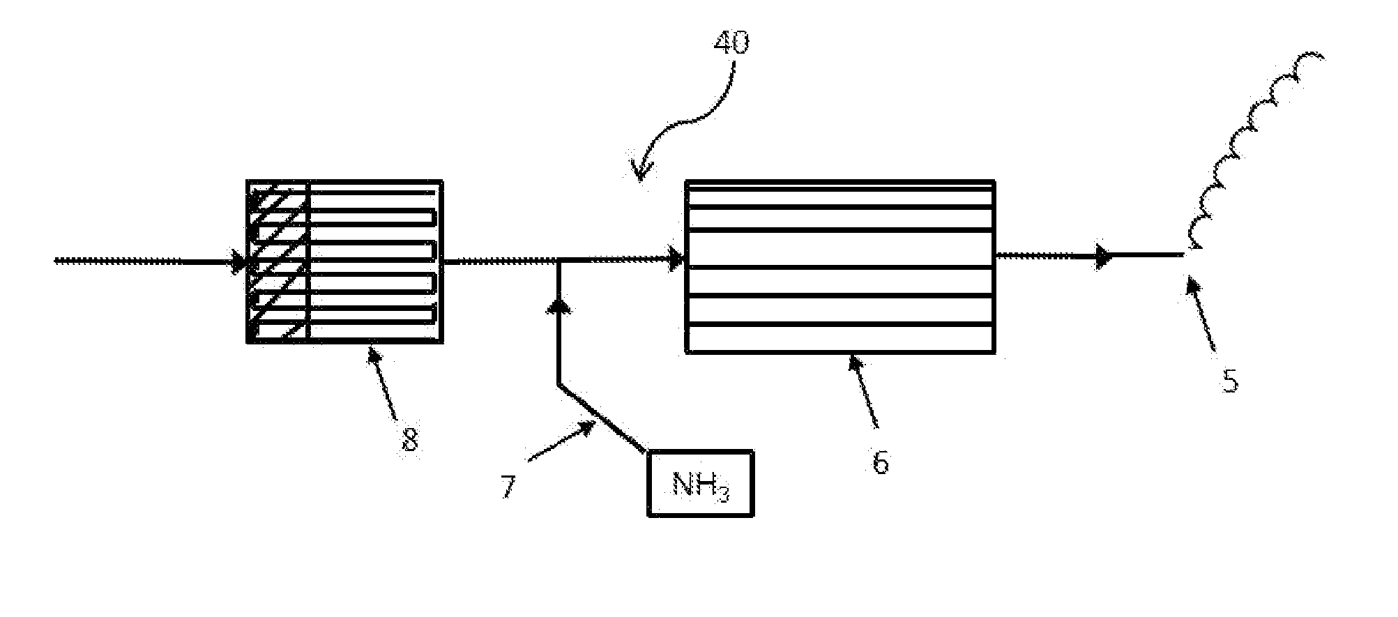
[0078]A catalysed soot filter according to the invention was prepared by coating a silicon carbide wallflow substrate of 5.66 inches (14.38 cm) diameter by 8 inches (20.32 cm) length having 300 cells per square inch (cpsi), 58% porosity and 22 μm pore size. Using established CSF coating techniques, 80% of the coating was applied over 80% of the substrate's axial length from the outlet end of the outlet channels and 20% of the coating was over 20% of the substrate's axial length from the inlet end of the inlet channels. The coating slurry comprised of platinum and palladium in a weight ratio of 10:1 supported on an alumina carrier. The filter was then oven aged in air at 750° C. for 5 hrs.

[0079]The platinum / palladium is present at a concentration of 10 g / ft3 and the on-wall coating composition has a washcoat loading of 0.55 g / in3 for both the inlet and outlet, with a D50 of less than or equal to 10 μm.

example 2

[0080]A comparative catalysed soot filter was prepared by coating the same silicon carbide wallflow substrate as used in Example 1 with the same coating as is described in Example 1, except in that 80% of the coating was applied over 80% of the substrate's axial length of the inlet channels from the inlet ends thereof and 20% of the coating was applied over 20% of the substrate's axial length from the outlet end of the outlet channels.

example 3

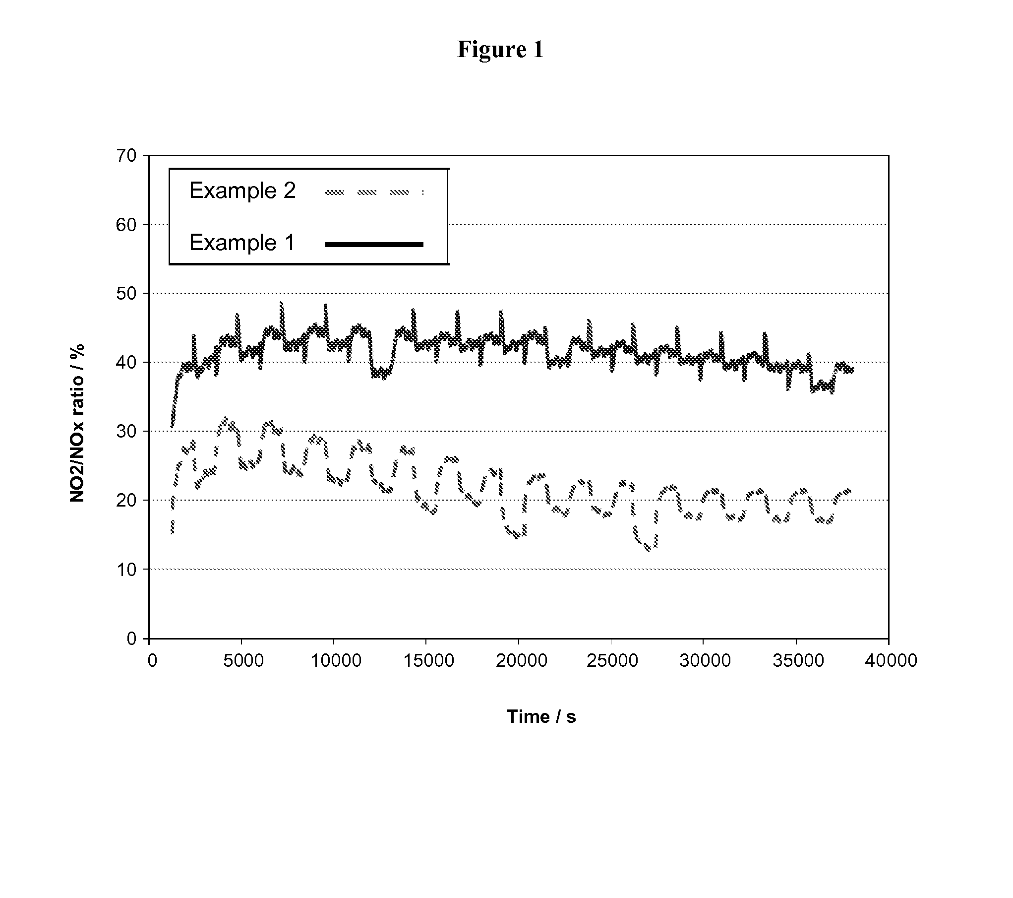
[0081]Both catalysed soot filters of Example 1 and Example 2 were exposed to exhaust emissions from a 2.0 litre turbo charged diesel bench engine using diesel fuel with 50 ppm sulphur content running a repeated transient cycle over a ten hour period, with a maximum catalysed soot filter inlet temperature of about 310 to 315° C.

[0082]FIG. 1 shows the percentage of NO2 in the NOx emitted from the catalysed soot filters of Example 1 and Example 2. It is clear from the results shown for Example 1 that when the coating composition is mostly present on the outlet wall there is a higher percentage of NO2 in the NOx exiting the catalysed soot filter. Furthermore, the percentage of NO2 exiting the catalysed soot filter is much more stable than that when the coating composition is mostly present on the inlet wall.

[0083]FIG. 1 clearly shows that diesel exhaust gas exiting the catalysed soot filter of the invention has the preferred composition of NO2 / NO of total NOx for effective treatment of ...


PUM

PropertyMeasurementUnit
Fractionaaaaaaaaaa
Fractionaaaaaaaaaa
Fractionaaaaaaaaaa

Abstract

A catalysed soot filter for a diesel engine comprises a wall flow substrate having a substrate axial length, wherein surfaces of both the internal walls of a plurality of inlet and a plurality of outlet channels comprise a catalytic washcoat of at least one on-wall coating composition for oxidising NO in exhaust gas to NO2, wherein the washcoat on the inlet channels extends for an axial inlet coating length from an open inlet end to a downstream inlet coating end, the washcoat on the outlet channels extends for an axial outlet coating length from an upstream outlet end to an open outlet end, the axial inlet coating length and the axial outlet coating length are both less than the substrate axial length and the outlet coating length is greater than the inlet coating length.

Description

CROSS REFERENCE TO RELATED APPLICATIONS[0001]This application claims priority benefit to Great Britain Patent Application No. 1219600.2 filed Oct. 31, 2012 and U.S. Provisional Patent Application No. 61 / 721,713 filed Nov. 2, 2012, both of which are incorporated herein by reference.FIELD OF THE INVENTION[0002]The present invention relates to a catalysed soot filter for treatment of diesel engine exhaust emissions which removes particulate matter (PM), hydrocarbons (HC) and carbon monoxide (CO) from the exhaust emissions and simultaneously enriches nitrogen dioxide (NO2) concentration in the oxides of nitrogen (NOx) emitted from diesel engines to enable more efficient treatment of such nitrogen oxides. The present invention also relates to an emission treatment system for a diesel engine comprising the catalysed soot filter and a selective catalytic reduction (SCR) catalyst downstream of the catalysed soot filter. The invention further relates to an emission treatment system for a die...

Claims


Application Information

Patent Timeline
IPC IPC(8): F01N3/035B01D53/94
CPCB01D53/9431F01N3/035B01J23/40B01D53/944B01D53/9472B01D53/9477B01J35/04F01N3/0222B01D2255/10B01D2255/9032B01D2255/9155F01N2510/06F01N3/0814F01N3/103F01N3/106F01N3/2066F01N2610/02F01N2510/068B01D53/9418B01D2255/1021B01D2255/1023B01D2255/2092B01J23/63B01J37/0215B01J23/48F01N2510/0682Y10S55/30Y02T10/12B01D53/9409
Inventor BROWN, GAVIN MICHAELCHIFFEY, ANDREW FRANCISMARVELL, DAVID
Owner JOHNSON MATTHEY PLC
Why Eureka
Try Eureka