Al technical title is built by PatSnap Al team. It summarizes the technical point description of the patent document.
a technology of reagent ion and generator, which is applied in the field of remote reagent ion generator, can solve the problems of no existing technology having such positional and potential independence of the source, and achieve the effect of small cross-sectional area and slow reaction kinetics
Inactive Publication Date: 2009-08-04
LEIDOS
View PDF147 Cites 87 Cited by
Summary
Abstract
Description
Claims
Application Information
AI Technical Summary
This helps you quickly interpret patents by identifying the three key elements:
Problems solved by technology
Method used
Benefits of technology
[0027]Another advantage of the present invention is its capability to generate a large excess of reagent ions in a remote region and to then introduce a high percentage of these reagent ions into the reaction region to drive the equilibrium of the reaction between reagent ions and sample far toward completion.
[0028]Another advantage of the present invention is the lack of limitations to the reaction volume. The reaction volume may literally be hundreds of cm3 and the sampling losses associated with conventional sources will not be experienced because of the highly efficient use of electric fields to collect and move ions.
[0029]Another advantage of this ion source is the capability for neutrals and reagent ions to reside in the reaction region, in the presence of low electrostatic fields, for relatively long durations, even in a large volume, thus allowing reactions with very slow reaction kinetics to proceed well towards completion.
[0030]Another advantage of the present device is its capability to utilize the tremendous compression capabilities of funnel-well optics to compress substantially all of the ions generated in the reaction and funnel regions into a small cross-sectional area.
[0031]Another advantage of the present invention is its capability to heat a sample on a surface by means of radiant heat from a light source, such as an infrared light, or a laser, inducing volatilization the sample, forming gas-phase molecules, and then reacting these gas-phase molecules with reagent ions to form gas-phase sample ions which are then delivered into a gas-phase ion analyzer, such as a mass spectrometer or ion mobility analyzer.
[0032]Another advantage of the present invention is its capability to deposit reagent ions on a surface thereby charging-up sample chemical species on the surface and thereafter using the electric potentials of the device to collect those charged sample ions into a low-field region, and to subsequently move those gas-phase sample ions into a gas-phase ion analyzer through an aperture or capillary tube while controlling the various operations by use of a computer to thereby optimize the timing of each event, and synchronizing all events.
Problems solved by technology
No existing technology has such positional and potential independence of the source.
Method used
Image
Click on the blue label to locate the original text in one second.
Reading with bidirectional positioning of images and text.
Examples
Embodiment Construction
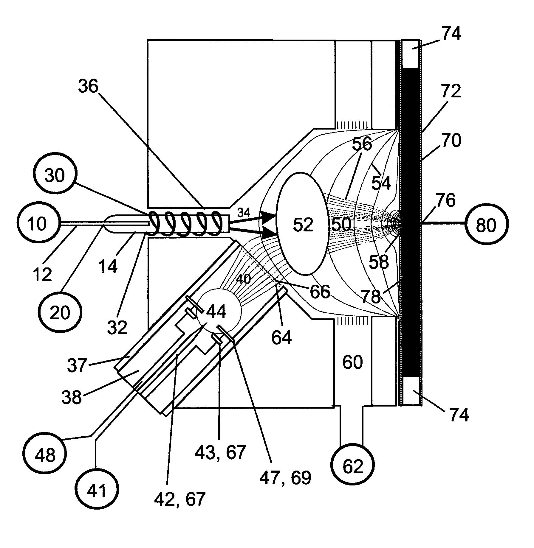
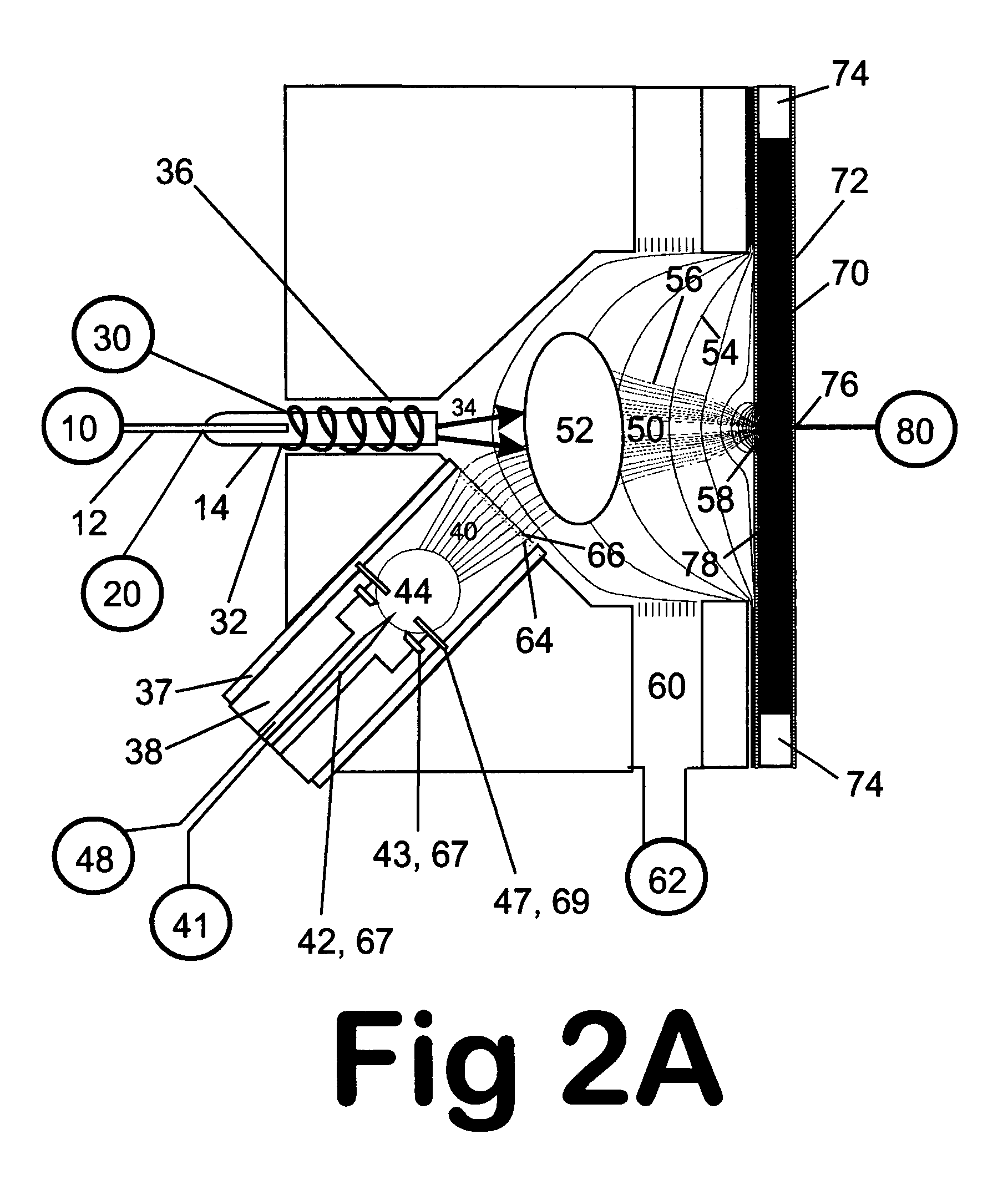
[0059]The invention will be described with reference to the drawing Figures in which FIGS. 1, 2A, 2B, and 2C illustrate a basic preferred embodiment of the invention that employs a Remote Reagent Chemical Ionization Source, hereafter referred to as a R2CIS.
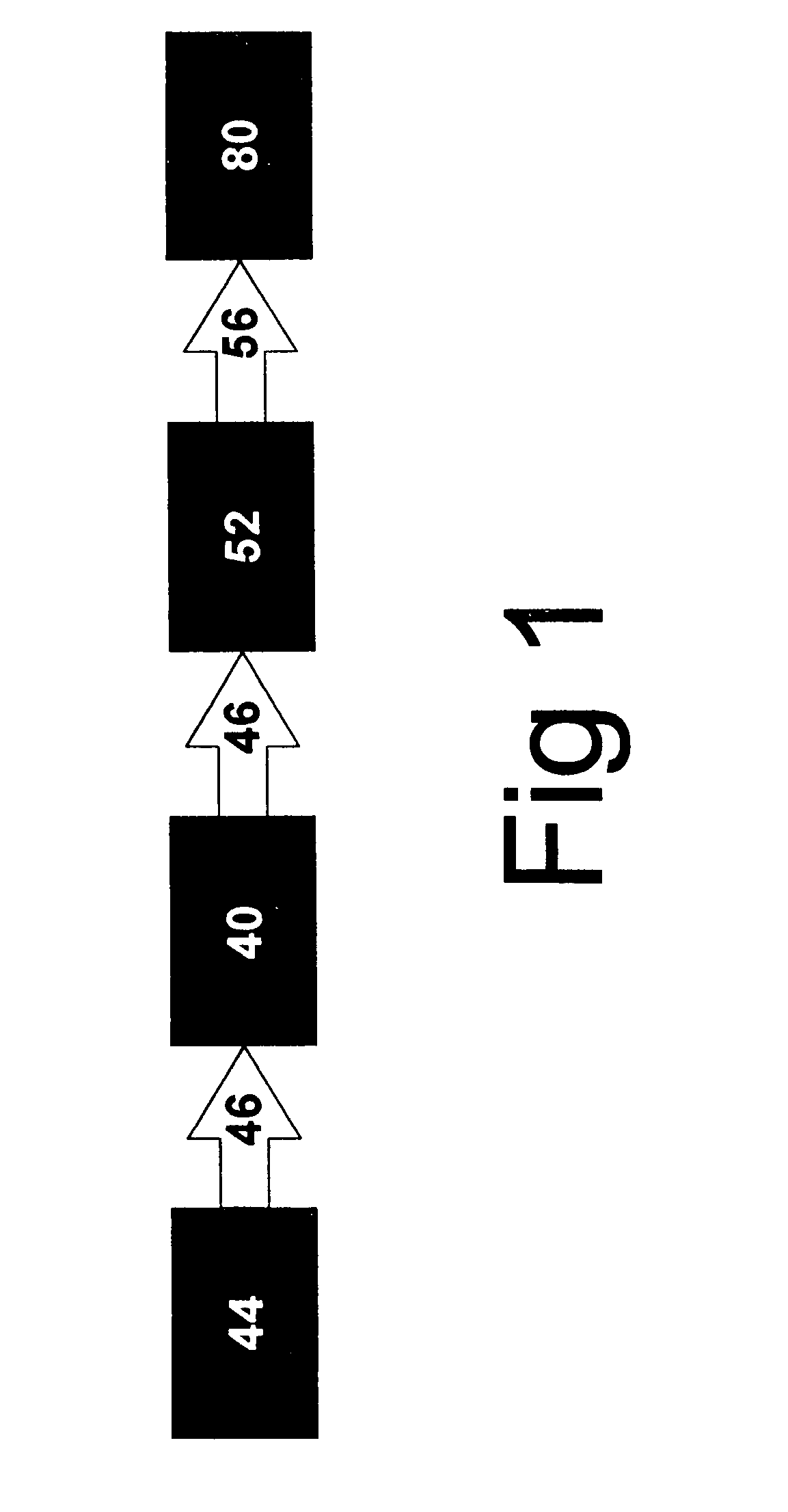
[0060]FIG. 1 shows the general sequence of hardware and events. Reagent ions are created in the R2CIS reagent ion source region 44 and move along ion trajectory 46 to a field-free transfer region 40. Passage of reagent ions into a reaction or sample ionization region 52 causes sample ions to be produced, which move via sample ion trajectories 56 to a sample ion collection region 80.
[0061]Referring now to FIG. 2A, reagent ion species are generated in the R2CIS reagent ion source region 44 by discharge ionization from a first electrode (needle) 42 biased relative to a second electrode 43. The voltage differential applied between the two discharge electrodes is supplied by a conventional high voltage supply source 67. Reagent gas is ...
PUM
Property
Measurement
Unit
diameter
aaaaa
aaaaa
diameter
aaaaa
aaaaa
aperture diameters
aaaaa
aaaaa
Abstract
An improved ion source and means for collecting and focusing dispersed gas-phase ions from a remote reagent chemical ionization source (R2CIS) at atmospheric or intermediate pressure is described. The R2CIS is under electronic control and can produce positive, negative, or positive and negative reagent ions simultaneously. This remote source of reagent ions is separated from a low-field sample ionization region by a stratified array of elements, each element populated with a plurality of openings, wherein DC potentials are applied to each element necessary for transferring reagent ions from the R2CIS into the low-field sample ionization region where the reagent ions react with neutral and / or ionic sample forming sample ionic species. The resulting sample ionic species are then introduced into a mass spectrometer, ion mobility spectrometer or other sensor capable of detecting the sample ions. Embodiments of this invention are methods and devices for improving sensitivity of mass spectrometry when gas and liquid chromatographic separation techniques are coupled to atmospheric and intermediate pressure photo-ionization, chemical ionization, and thermospray ionization sources; and improving the sensitivity of chemical detectors or probes.
Description
REFERENCE TO RELATED APPLICATIONS[0001]This application claims the benefit of U.S. Provisional Patent Application No. 60 / 724,399 that was filed on Oct. 7, 2005.[0002]This patent also relates to the following commonly owned patents and patent applications: U.S. Pat. No. 6,888,132, granted May 3, 2005 and continuation Ser. No. 11 / 120,363, filed May 2, 2005 now U.S. Pat. No. 7,095,019. This application is also related to application Ser. No. 08 / 946,290, filed Oct. 7, 1997, now U.S. Pat. No. 6,147,345, granted Nov. 14, 2000; application Ser. No. 09 / 877,167, filed Jun. 8, 2001, now U.S. Pat. No. 6,744,041, granted Jun. 1, 2004; application Ser. No. 10 / 449,147, filed May 31, 2003, now U.S. Pat. No. 6,818,889, granted Nov. 16, 2004; application Ser. No. 10 / 785,441, filed Feb. 23, 2004, now U.S. Pat. No. 6,878,930, granted Apr. 12, 2005; application Ser. No. 10 / 661,842, filed Sep. 12, 2003, application Ser. No. 10 / 688,021, filed Oct. 17, 2003, application Ser. No. 10 / 863,130, filed Jun. 7, ...
Claims
Application Information
Patent Timeline
Application Date:The date an application was filed.
Publication Date:The date a patent or application was officially published.
First Publication Date:The earliest publication date of a patent with the same application number.
Issue Date:Publication date of the patent grant document.
PCT Entry Date:The Entry date of PCT National Phase.
Estimated Expiry Date:The statutory expiry date of a patent right according to the Patent Law, and it is the longest term of protection that the patent right can achieve without the termination of the patent right due to other reasons(Term extension factor has been taken into account ).
Invalid Date:Actual expiry date is based on effective date or publication date of legal transaction data of invalid patent.
Patent Type & Authority Patents(United States)
IPC IPC(8): B01D59/44H01J49/00
CPCH01J49/0468H01J49/145H01J49/067
Inventor KARPETSKY, TIMOTHY P.BERENDS, JR., JOHN C.SHEEHAN, EDWARD W.WILLOUGHBY, ROSS C.