A method and device for grinding a spherical surface on an ordinary lathe

A common lathe and grinding technology, used in spherical grinders, grinding/polishing equipment, grinders, etc., can solve the problem of inability to process split bearings, etc., and achieve the effect of a wide range of applications

Inactive Publication Date: 2015-09-02
ANSTEEL HEAVY MACHINERY CO LTD
View PDF3 Cites 0 Cited by
  • Summary
  • Abstract
  • Description
  • Claims
  • Application Information

AI Technical Summary

Problems solved by technology

[0002] In the current manufacturing of mechanical equipment, there are many workpieces with spherical raceways that need to be ground, such as the Φ900 bearing on the converter in the steelmaking plant, the three-point split ball hinge seat, and the convex-concave spherical pad in the hanging device. They must be processed by a special arc raceway spherical surface grinder, especially the Φ460 split ball joint in the three fulcrums of the converter, which determines the stability of the furnace body rotation. The design precision of the spare parts is high, and the sphericity error is ±0.02mm. , The contact area of ​​the outer spherical surface must be ≥ 75%, the material is GCr15SiMn, the hardness after quenching is HRc50-55, and the surface roughness is Ra0.8. In the past, it was imported from abroad. Domestic bearing factories cannot process such split bearings, especially in the absence of In the case of special spherical grinding machines, it is necessary to solve the grinding problems of such products on ordinary lathes

Method used


Image

  • A method and device for grinding a spherical surface on an ordinary lathe
  • A method and device for grinding a spherical surface on an ordinary lathe
  • A method and device for grinding a spherical surface on an ordinary lathe

Examples


Embodiment Construction

[0022] The specific embodiment of the present invention will be further described below in conjunction with accompanying drawing:

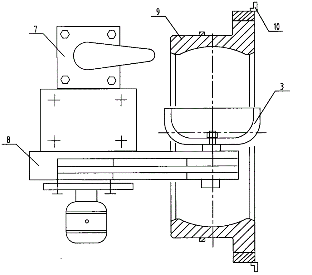
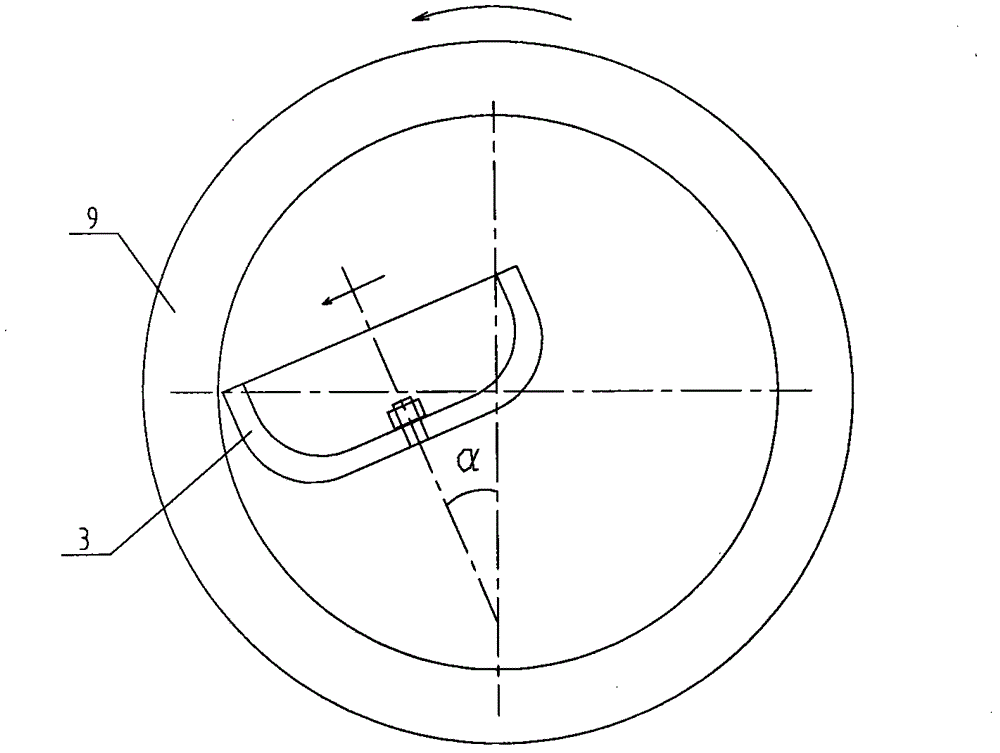
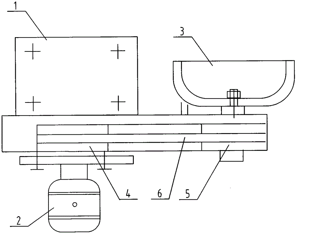
[0023] See figure 1 , figure 2 , a schematic diagram of the embodiment of a method for grinding a spherical surface on an ordinary lathe according to the present invention. The grinding of the inner spherical surface is taken as an example to illustrate. According to the principle that two circles intersect to form a spherical surface, a special radial tool is installed on the tool holder with an ordinary lathe. The grinding head uses a Φ250mm cup-shaped grinding wheel. When grinding, the radial grinding head performs radial grinding, that is, it grinds out an ideal spherical surface. The operation steps are described as follows:

[0024] 1), the radial grinding head 8 is installed on the ordinary lathe tool rest 7, the workpiece 9 is clamped on the ordinary lathe chuck 10, the rotation center line of the emery wheel 3 on the radial grinding hea...


PUM


Abstract

The invention relates to a method and a device for grinding a spherical surface on an engine lathe. The invention is characterized in that the spherical surface is ground by using a radial grinding head device on the basis of a principle that two circles intersect to form the spherical surface. The method comprises the following steps of: 1) arranging a radial grinding head on a lathe tool holder, and arranging a workpiece on a chuck; 2) setting grinding parameters, wherein the speed V sand of a grinding wheel is 18 meters / second, the speed V workpiece of the workpiece is between 6 and 8 meters / minute, the workpiece rotates 2 to 4 circles, and the grinding depth t is between 5 and 10 micrometers; 3) ensuring that the height of a center of the grinding wheel is equal to that of revolution center of the workpiece; and 4) inspecting by using a sample plate. A motor on the radial grinding head is connected with a belt wheel I and a base sequentially; a belt wheel II is connected with the base and the grinding wheel sequentially; and the belt wheel I is connected with the belt wheel II by a belt. Compared with the prior art, the method has the advantage that ideal spherical surface bodies of different specifications are ground on the engine lathe according to the principle of forming the spherical surface, so the method has a wide application range, and the problem that the spherical surface is difficult to grind under the condition of no special spherical surface grinder.

Description

technical field [0001] The invention relates to the field of mechanical processing, in particular to a method and device for grinding a spherical surface on a common lathe. Background technique [0002] In the current manufacturing of mechanical equipment, there are many workpieces with spherical raceways that need to be ground, such as the Φ900 bearing on the converter in the steelmaking plant, the three-point split ball hinge seat, and the convex-concave spherical pad in the hanging device. They must be processed by a special arc raceway spherical grinder, especially the Φ460 split ball joint in the three fulcrums of the converter, which determines the stability of the furnace body rotation. The design accuracy of the spare parts is high, and the sphericity error is ±0.02mm. , The contact area of ​​the outer spherical surface must be ≥ 75%, the material is GCr15SiMn, the hardness after quenching is HRc50-55, and the surface roughness is Ra0.8. In the past, it was imported ...

Claims


Application Information

Patent Timeline
Patent Type & Authority Patents(China)
IPC IPC(8): B24B11/04
Inventor 王晓平李锡增田强高扬
Owner ANSTEEL HEAVY MACHINERY CO LTD
Why Eureka
Try Eureka