Ten-step self-equalization Ku frequency-band dielectric filter

A dielectric filter and self-equalization technology, applied in waveguide-type devices, electrical components, circuits, etc., can solve the problems of reducing product reliability and increasing the difficulty of debugging, improving reliability, reducing the amount of debugging, and overcoming parasitic coupling. Effect

Active Publication Date: 2012-03-28
XIAN INSTITUE OF SPACE RADIO TECH
View PDF5 Cites 10 Cited by
  • Summary
  • Abstract
  • Description
  • Claims
  • Application Information

AI Technical Summary

Problems solved by technology

[0004] Searched the relevant literature, but did not find domestic literature on dielectric filter parasitic coupling overcoming technology. There are still many articles or patents introducing TE01 mode dielectric filters in the world, but there is only one related to the tenth order self-equalizing dielectric filter. Article patent International patent WO 95 / 27317, such as Figure 10 As shown, the patent introduces redundant cross-coupling to overcome the influence of parasitic coupling. The disadvantage of this approach is that due to the introduction of redundant cross-coupling, product reliability is reduced. In addition, redundant cross-coupling is often determined during the debugging phase size, which increases the difficulty of debugging

Method used


Image

  • Ten-step self-equalization Ku frequency-band dielectric filter
  • Ten-step self-equalization Ku frequency-band dielectric filter
  • Ten-step self-equalization Ku frequency-band dielectric filter

Examples


Embodiment Construction

[0026] Specific embodiments of the present invention will be described in detail below in conjunction with the accompanying drawings.

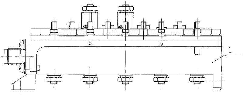
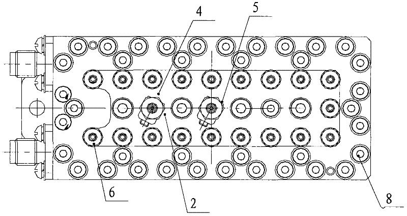
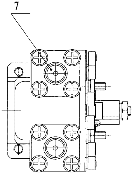
[0027] The transfer function of the TE01 module tenth-order self-equalizing Ku-band dielectric filter of the present invention adopts the form of 10-4-4, that is, the filter has 8 transmission zeros, 4 of which are used for delay equalization and 4 for out-of-band suppression pole, the synthesis of its coupling matrix is ​​the same as that of a typical generalized Chebyshev filter, and the existing self-programmed or commercial software can obtain the filter coupling matrix that meets the index requirements. After synthesis, the main couplings in the coupling matrix are all positive, two negative cross-couplings are respectively located between dielectric resonators R2 and R9, R3 and R8, and one positive cross-coupling is located between dielectric resonators R1 and R10.

[0028] Such as figure 1 , 2 , 3, 4, and 5, the tenth-order self-bala...


PUM


Abstract

The invention discloses a ten-step self-equalization Ku frequency-band dielectric filter. The filter comprises a cavity body (1), a cover plate (2), dielectric resonators (3), a dual-layer U-shaped coupling probe (4), a single-layer U-shaped coupling probe (5), a tuning screw (6), an SMA (surface mounted assembly) electrical connector (7) and a fastening screw (8). The cross coupling between the dielectric resonators R2 and R9 is realized by adopting a novel U-shaped double-layer negative coupling probe, and the cross coupling between the dielectric resonators R3 and R8 is realized by adopting a traditional single-layer U-shaped probe; and through regulating the lengths of the probes on the upper layer and the lower layer of the double-layer U-shaped probe, the influence of spurious coupling can be overcome, thus the transmission response of the filter is symmetrical.

Description

technical field [0001] The invention relates to a ten-order self-equalizing Ku-band dielectric filter, in particular to a TE01-mode ten-order self-equalizing Ku-band dielectric filter, which belongs to the field of microwave passive components. Background technique [0002] TE01 mode tenth-order self-equalizing Ku-band dielectric filter has the characteristics of small size, light weight, small insertion loss, flat in-band, and high out-of-band rejection. It is mainly used as a channel filter of a multiplexer to form an input multiplexer. The network can also be used as a filter alone to filter signals in a certain frequency band. Its application can greatly increase the number of channels of the communication satellite transponder subsystem. [0003] The TE01-mode tenth-order self-equalizing Ku-band dielectric filter has high order and many cross-couplings, and the parasitic coupling is very rich, especially the parasitic coupling caused by the cross-negative coupling will ...

Claims


Application Information

Patent Timeline
Patent Type & Authority Applications(China)
IPC IPC(8): H01P1/208
Inventor 梁军利胡浩张燚杨毅民殷新社孙公科
Owner XIAN INSTITUE OF SPACE RADIO TECH
Why Eureka
Try Eureka