
Gear Lever Device

A technology for shift levers and transmissions, which is applied to control devices, transmission control, transportation and packaging, etc. It can solve the problems of not being able to obtain a good operating feeling of the shift lever, achieve lightweight, prevent the increase in the number of components, and improve reliability Effect

Active Publication Date: 2012-04-11
KNORR BREMSE COMML VEHICLE SYST JAPAN
View PDF6 Cites 4 Cited by
  • Summary
  • Abstract
  • Description
  • Claims
  • Application Information

AI Technical Summary

Problems solved by technology

Therefore, it is considered that when the shift lever is operated, the parking cable is often dragged, and a good operating feeling of the shift lever cannot be obtained.

Method used


Image

  • Gear Lever Device
  • Gear Lever Device
  • Gear Lever Device

Examples


Embodiment Construction

[0026] Hereinafter, modes for implementing the present invention will be described using the drawings.

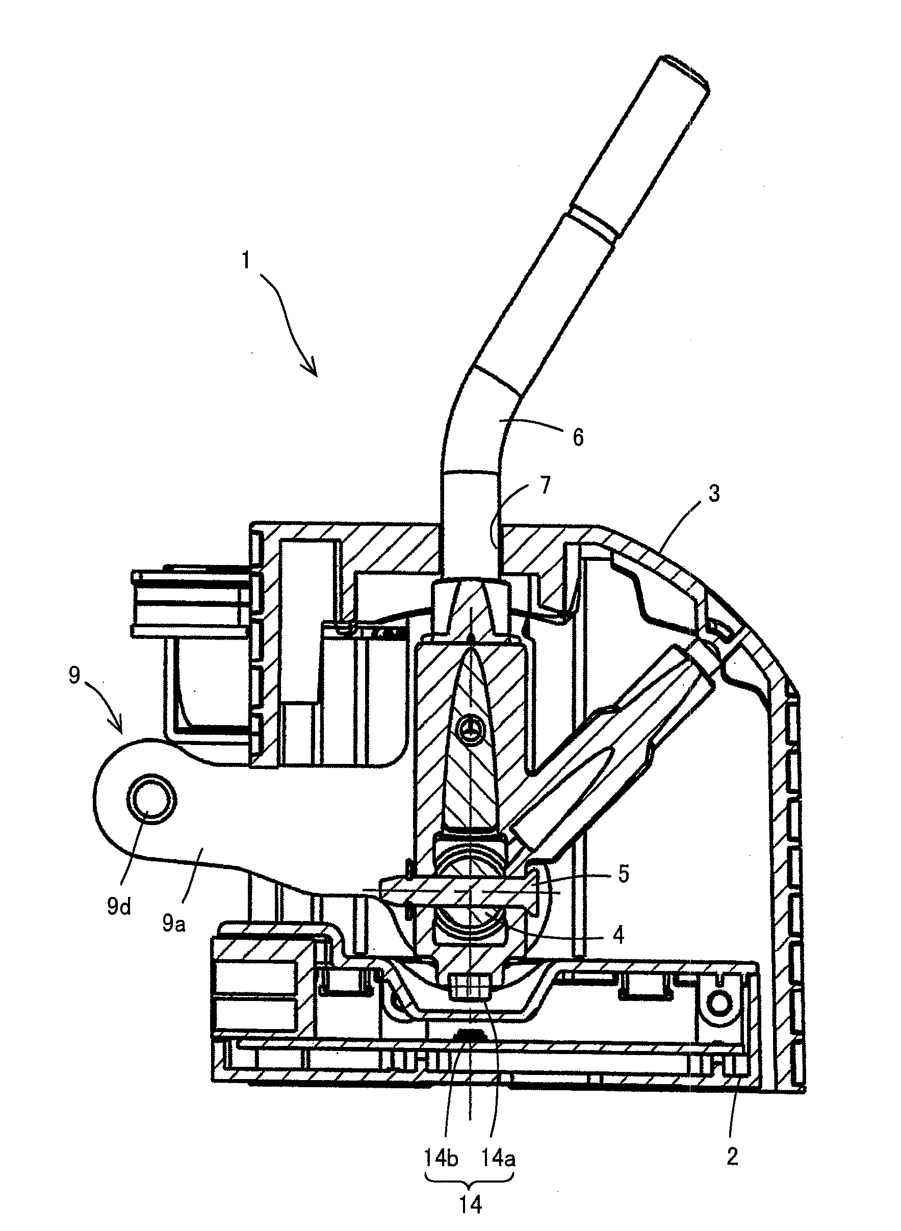
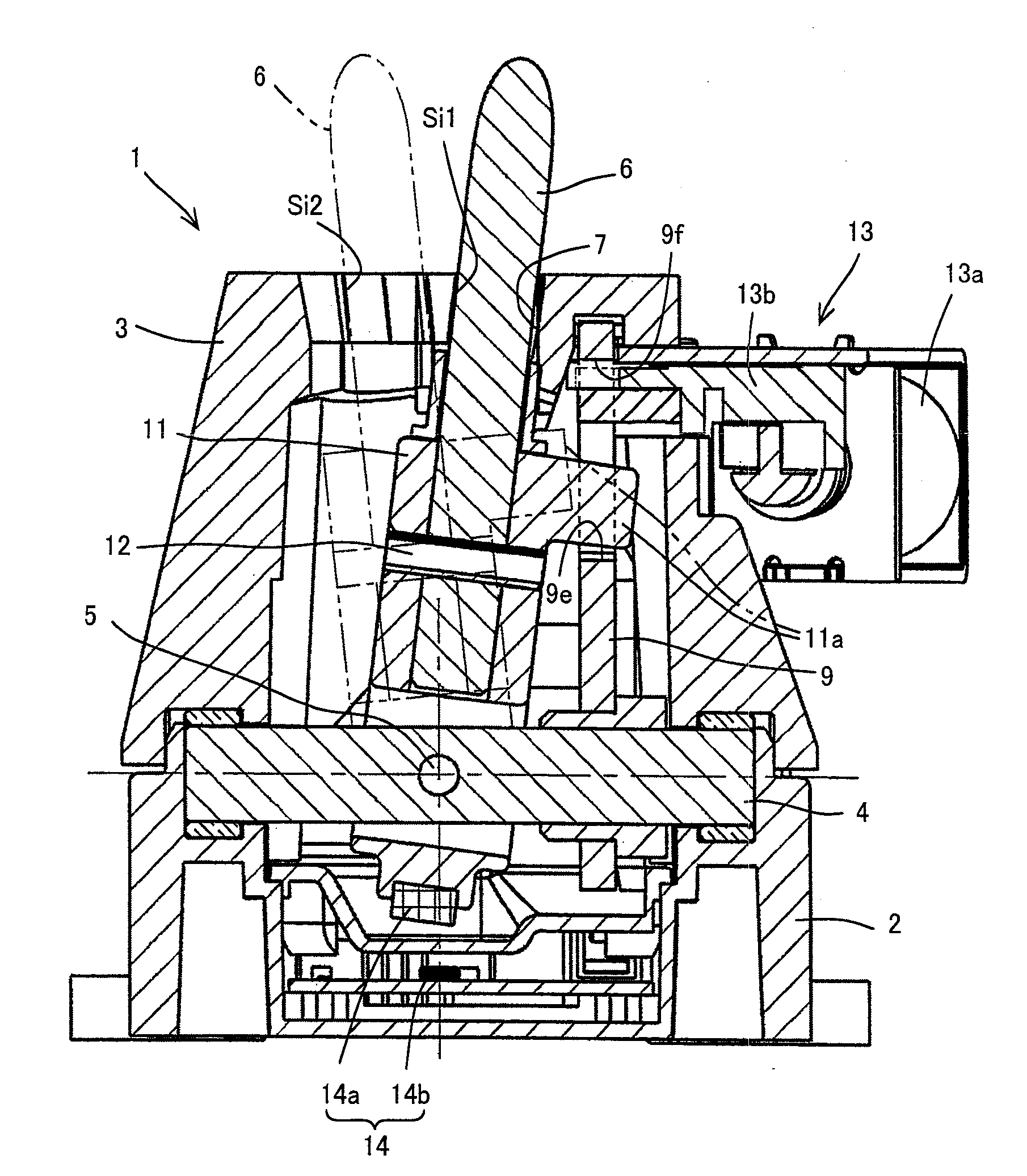
[0027] figure 1 An example showing an embodiment of the shift lever device according to the present invention is a longitudinal sectional view passing through the center of the shift rotation shaft; figure 2 is a longitudinal sectional view passing through the center of the selector rotary shaft of the shift lever device of this example.

[0028] Such as figure 1 and figure 2 As shown, the shift lever device (CLU: Change Lever Unit) 1 of this example includes: a container-shaped device body 2 constituted as a sensor structure; The upper end of the device body 2 is open.

[0029] Inside the device body 2, a shift rotation shaft 4 is rotatably provided around its center axis. In addition, a gear selection rotating shaft 5 is inserted through the shifting rotating shaft 4 , and is perpendicular to the shifting rotating shaft 4 . Further, one end portion of the shift le...


PUM


Abstract

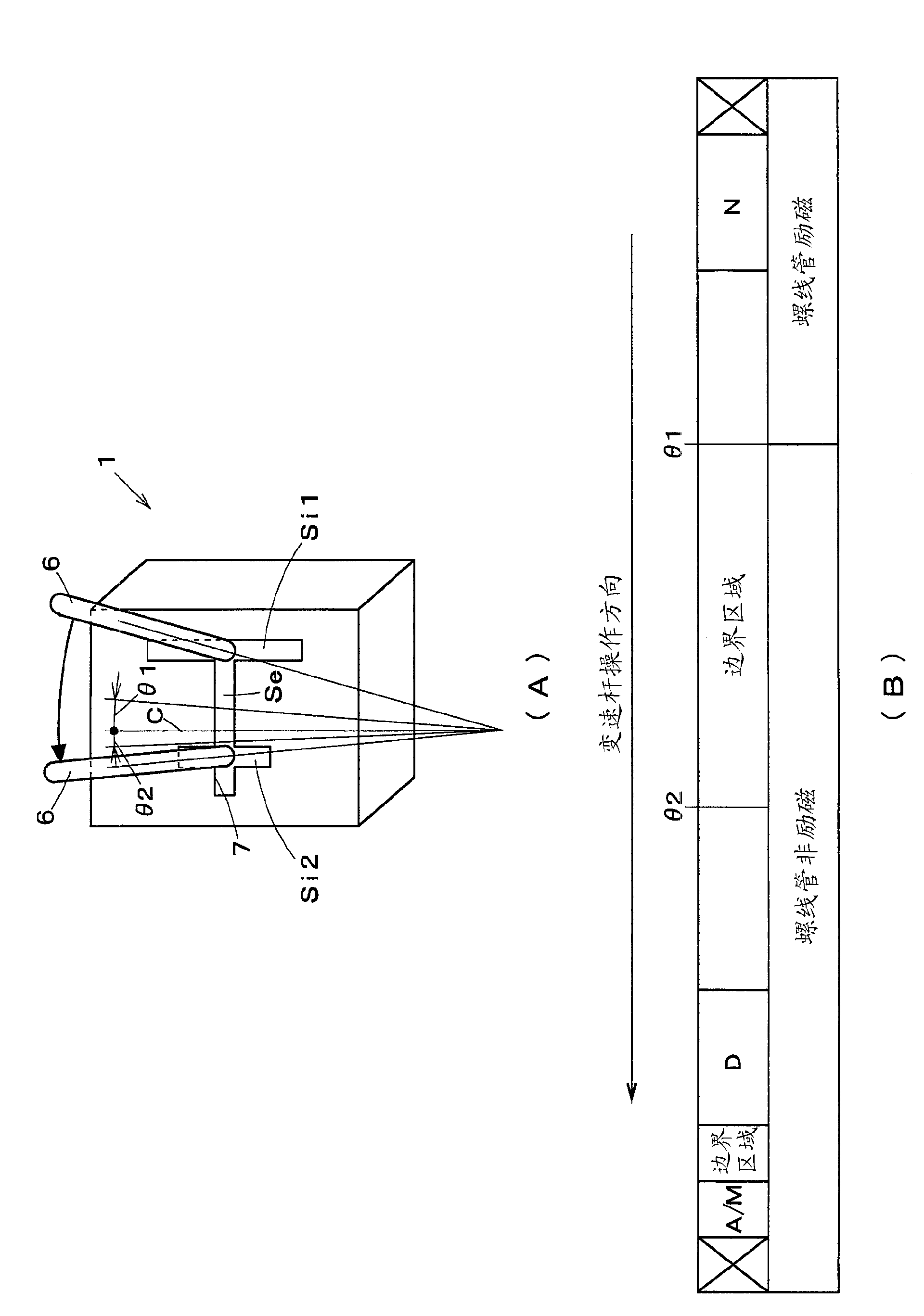
The invention provides a gear lever device. A snap separating unit (11) of the gear lever device snaps the gear lever (6) and a parking rod (9) connecting with a transmission locking unit through a parking cable when determining the gear lever (6) in a first gear shift column (Si1) having a parking gear position. Besides, the snap separating unit (11) separates the gear lever (6) and a parking rod (9) when the gear lever (6) is set in second gear shift column (Si2) but not the first gear shift column (Si1). Thus, when the second gear shift column (Si2) is operated, the operation of the gear lever (6) is not affected by a sliding resistance of the parking cable. And the operation experience of the gear lever (6) becomes good.

Description

technical field [0001] The present invention relates to the technical field of a shift lever device operated for shift control of a transmission. Background technique [0002] Conventionally, in a vehicle transmission, Japanese Patent Application Laid-Open No. 2009-274486 has known a shift lever device having a plurality of shift rows arranged in parallel with each other and each having a plurality of shift positions (gear positions), and These shift rows are connected vertically and have a plurality of shift positions (gear positions), and a shift layout is set in which a shift lever is operated in a shift direction and a shift direction. In addition, JP-A-2009-292387 is also known in which a shift lever device is formed in a crank shape and a shift layout in which a shift lever is operated along the crank shape is set. [0003] In general, in conventional shift lever devices, the shift lever is always connected to the transmission lock unit via a parking cable, and when t...

Claims


Application Information

Patent Timeline
IPC IPC(8): B60K20/02F16H59/02
CPCF16H59/0204F16H59/105B60K20/00B60K20/02
Inventor 菅野淳赤羽哲男
Owner KNORR BREMSE COMML VEHICLE SYST JAPAN
Learn More