Heat pump drying device

A technology of heat pump drying and drying oven, which is applied in the direction of drying gas arrangement, drying solid materials, local agitation dryers, etc. It can solve the problems of temperature, humidity and wind speed requirements difference, increase energy consumption, reduce product quality and other problems, and achieve improvement Effect of drying quality, improving drying speed, and ensuring quality

Inactive Publication Date: 2012-04-11
SOUTH CHINA UNIV OF TECH
View PDF5 Cites 21 Cited by
  • Summary
  • Abstract
  • Description
  • Claims
  • Application Information

AI Technical Summary

Problems solved by technology

At present, the problem faced by heat pump drying is that different materials have quite different requirements on temperature, humidity and wind speed during the drying process. Even the same material has different properties in different drying stages.
If the material is dried with constant temperature and humidity, it will not only reduce the production efficiency, but also increase the energy loss and reduce the quality of the product.

Method used


Image

  • Heat pump drying device
  • Heat pump drying device

Examples


Embodiment

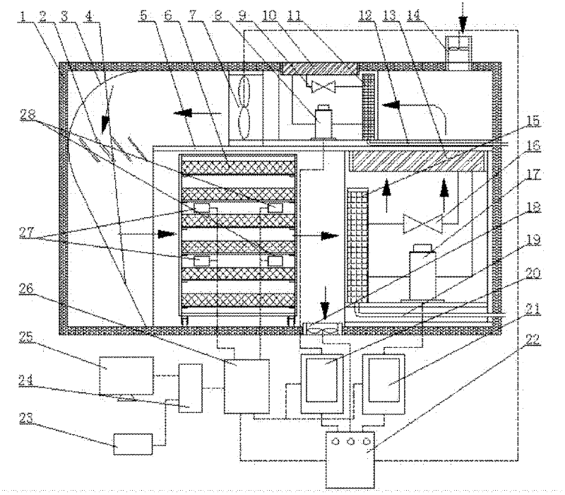
[0021] like figure 1 As shown, the heat pump drying device of the present invention includes a drying box and a control system. The drying box includes a housing 1 and an air inlet fan 14 disposed in the housing 1, a dehumidification heat pump, a main fan 7, a material rack 6, an exhaust air Air blower 18 and heating heat pump. Air inlet fan 14, dehumidification heat pump, main fan 7, air outlet fan 18, and heating heat pump are all connected with the control system. The top of the casing 1 is provided with an air inlet, and the air inlet fan 14 is located in the air inlet. The dehumidifying heat pump and the main fan 7 are arranged on the upper part of the housing 1, separated from the material rack 6 and the heating heat pump arranged on the lower part of the housing 1 by a partition 5. The upper part of the housing 1 is provided with an arc-shaped baffle 3 perpendicular to the front and rear surfaces of the housing in the direction facing the exhaust outlet of the main fa...


PUM


Abstract

The invention discloses a heat pump drying device, which comprises a drying box and a control system, wherein the drying box comprises a shell and an air inlet fan, a dehumidifying heat pump, a main fan, a material shelf, an air outlet fan and a heating heat pump which are arranged in the shell; when an air inlet and an air outlet are closed, the dehumidifying heat pump, the main fan, the material shelf, the heating heat pump and the dehumidifying pump are communicated in sequence, and a circulating path of a drying medium is formed in the shell; when the air inlet and the air outlet are opened, the air outlet, the dehumidifying heat pump, the main fan, the material shelf and the air outlet are communicated in sequence to form a one-way circulating path of the drying medium; and an air path between the main fan and the material shelf is arc-shaped, and an inclined air deflector is arranged in the air path. The heat pump drying device can not only realize high-temperature drying but also realize low-temperature drying and can meet temperature and humidify requirements of the same product at different drying stages; and the air path for communicating the main fan with the material shelf and the air deflector is improved, therefore airflow vortex is reduced, and drying quality and speed are increased.

Description

technical field [0001] The invention relates to a drying device, in particular to a heat pump drying device. Background technique [0002] The drying industry is an industry that consumes a lot of energy. In developed countries, about 10% to 20% of the fuel is used in the drying process. The heat pump is a device that consumes a part of low-grade energy as compensation to transfer heat energy from a low-temperature heat source to a high-temperature heat source. Compared with the traditional drying method, the heating coefficient of performance (COP) of the heat pump can reach more than 3.8, and the heat pump drying has high efficiency. Features of energy saving, low cost, and no pollution to the environment. Moreover, the dehumidification effect of the heat pump is obvious, and the material can be dried quickly at room temperature, thereby ensuring the quality and color of the dried material and producing high-quality products. At present, the problem faced by heat pump dr...

Claims


Application Information

Patent Timeline
Patent Type & Authority Applications(China)
IPC IPC(8): F26B9/06F26B21/00F26B25/22
Inventor 冯毅车本佳
Owner SOUTH CHINA UNIV OF TECH
Why Eureka
Try Eureka