Centralized monitoring method for optical cable resource

A centralized monitoring, optical cable technology, applied in transmission monitoring/testing/fault measurement systems, electromagnetic wave transmission systems, electrical components, etc., can solve problems such as economic loss, storage, and inability to provide strong support for optical cable planning, and reduce line Failure rate and line failure time, powerful data management function, the effect of improving line communication efficiency and line maintenance efficiency

Active Publication Date: 2012-04-11
SHANGHAI MUNICIPAL ELECTRIC POWER CO +1
View PDF4 Cites 18 Cited by
  • Summary
  • Abstract
  • Description
  • Claims
  • Application Information

AI Technical Summary

Problems solved by technology

With the help of existing optical fiber transmission equipment, it is possible to find a fault in a certain route, but it is impossible to quantify and locate the location of the fault, which will inevitably delay the time to deal with the fault and cause large economic losses; Provide strong support for optical cable planning
As a passive transmission medium, the optical cable has not yet developed its own detection and alarm function, and can only rely on an external system to monitor and manage its status
[0007] At the same time, because the traditional maintenance management is mainly written, it cannot be stored in the computer system, resulting in the accumulation of various reports and data, which is very inconvenient for inspection and comparison
In addition, since the construction and use are different units or departments, there may be some differences in the data collected in the organization of testing and acceptance, which will leave flaws for the later analysis of optical cable status changes and the formulation of update plans.

Method used


Image

  • Centralized monitoring method for optical cable resource
  • Centralized monitoring method for optical cable resource
  • Centralized monitoring method for optical cable resource

Examples


Embodiment Construction

[0061] Embodiments of the present invention will be described in detail below in conjunction with the accompanying drawings.

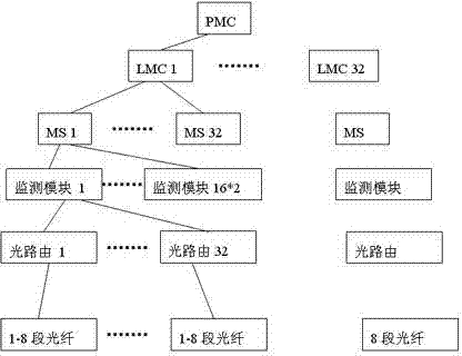
[0062] Such as figure 1As shown, an embodiment of the centralized monitoring system for optical cable resources applicable to the centralized monitoring method for optical cable resources of the present invention. The system in this embodiment comprises a provincial or municipal monitoring center PMC, a provincial or municipal monitoring center PMC is connected and monitored with 1 to 32 local monitoring centers LMC, each local monitoring center LMC is connected And monitor 1 to 32 monitoring stations MS, and each monitoring station MS connects and monitors 16*2 monitoring modules, each monitoring module connects and detects 32 optical routes, and each optical route connects and monitors 1 Up to 8 sections of optical fibers, so that the maximum system capacity configuration can reach: 32*32*16*32*8=4194304 (roots) optical fibers.

[0063] The system ...


PUM


Abstract

The invention discloses a centralized monitoring method for the optical cable resource. The method comprises the following steps of: 1, establishing an optical cable section; 2, establishing optical routing; 3, forming optical cable network topology; 4, setting a monitoring module for a network; 5, selecting a monitoring mode, skipping to a step 5.1 in a roll-call monitoring mode, skipping to a step 5.2 in an automatic periodic monitoring mode, and skipping to a step 5.3 in a barrier alarm monitoring mode; 5.1, performing roll-call monitoring at the optical cable section; 5.2, automatically and periodically monitoring the optical cable section; 5.3, performing barrier alarm monitoring at the optical cable section; 6, monitoring central analysis testing data, judging whether a fault occurs, skipping to a step 7 if the fault occurs, and skipping to the step 5 if no fault occurs; 7, assigning a person to maintain the failed optical cable section; and 8, monitoring the maintained optical cable section by using the monitoring module, and skipping to the step 5. In the method, online monitoring, analysis and real-time fault alarm are performed on a communication optical cable and communication equipment, so that the line communication and maintenance efficiencies are increased, the line failure rate is lowered, and the fault time is shortened.

Description

technical field [0001] The invention relates to an optical cable monitoring technology, in particular to a centralized monitoring method for optical cable resources. Background technique [0002] Optical fiber communication has a series of advantages in terms of transmission distance, transmission rate and stability, etc. Its application has increasingly penetrated into various fields of national economy and daily life, and has become an indispensable link. Since the optical fiber is a physical body, it has the life problem of performance degradation, coupled with the impact of various accidents, the optical cable is damaged, interrupted or affects communication. Therefore, it is more important to effectively predict the change trend of optical cables, judge and deal with optical fiber failures in a timely manner, and reducing the failure time of optical cables has become an important means to improve communication quality, ensure safe operation of power grids, and increase ...

Claims


Application Information

Patent Timeline
Patent Type & Authority Applications(China)
IPC IPC(8): H04B10/08H04B10/07
Inventor 张黎首林亦雷卢士达
Owner SHANGHAI MUNICIPAL ELECTRIC POWER CO
Why Eureka
Try Eureka