Steel rail deflection adjusting device and long steel rail train set

An adjustment device and long rail technology, applied in the field of rail trains, can solve problems such as heavy weight, long rail length, and downward bending, and achieve the effects of convenient transportation, improved transportation efficiency, and optimized structure

Active Publication Date: 2012-04-18
CRRC SHENYANG CO LTD
View PDF5 Cites 2 Cited by
  • Summary
  • Abstract
  • Description
  • Claims
  • Application Information

AI Technical Summary

Problems solved by technology

[0004] The existing long rail train set has the following problems in the process of transporting long rails: during transportation, the long rails move along the rail unloading guide grooves, and when the long rails move to the gap between the two sections of rail unloading guide grooves

Method used


Image

  • Steel rail deflection adjusting device and long steel rail train set
  • Steel rail deflection adjusting device and long steel rail train set
  • Steel rail deflection adjusting device and long steel rail train set

Examples


Example Embodiment

[0033] The steel rail deflection adjusting device provided by the present invention is suitable for being installed on a train in operation of a long rail train set or a train with a similar structure. The steel rail deflection adjustment referred to in the present invention refers to the suppression of excessive downward bending of the long steel rail.

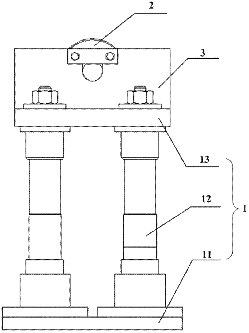
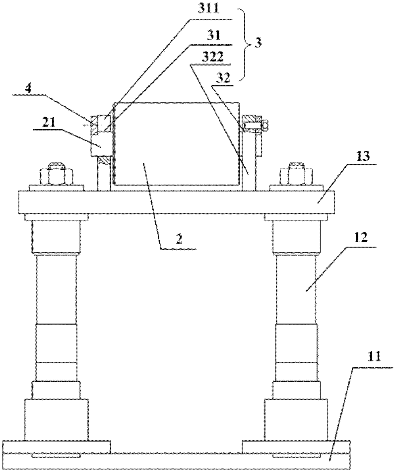
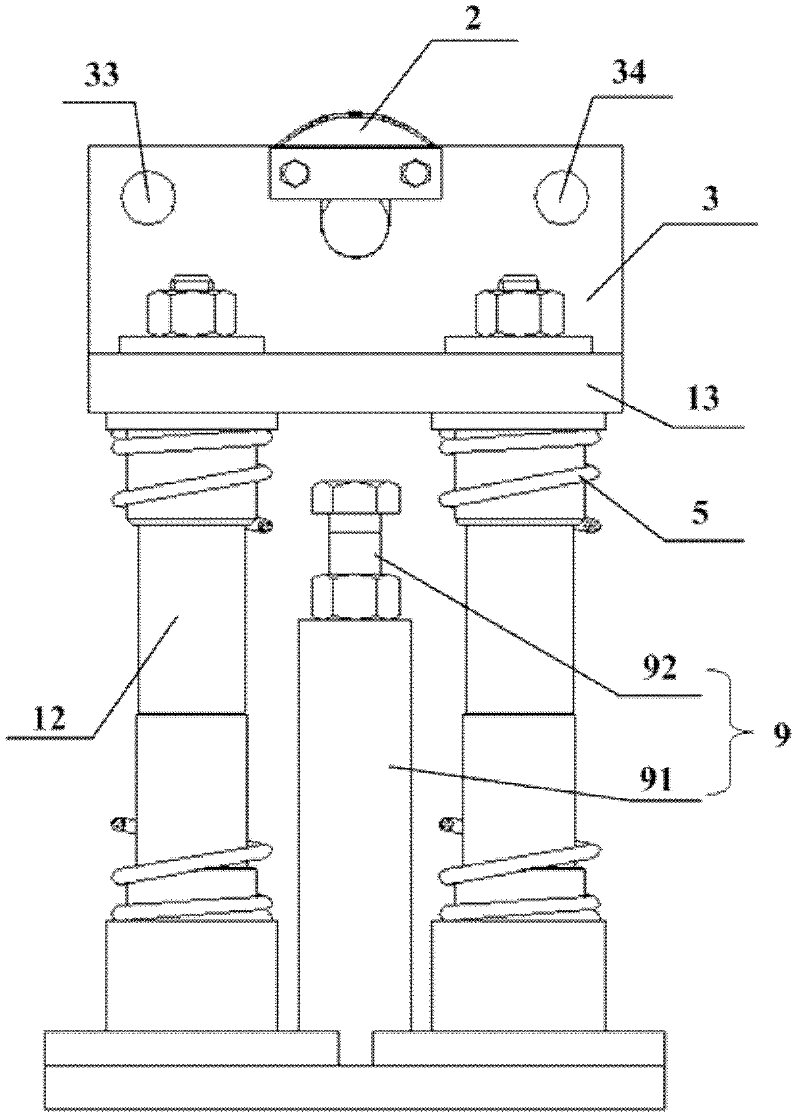
[0034] Figure 1a It is a schematic structural diagram of the first embodiment of the rail deflection adjusting device of the present invention, Figure 1b for Figure 1a Left view. See Figure 1a with Figure 1b The rail deflection adjustment device has a support table 1 on which a roller 2 is provided. The roller 2 is used to carry the long rail to be transported, and the roller resistance is small.

[0035] The rail deflection adjustment device is used to install between two sections of rail unloading guide grooves. The long rail slides along the unloading guide groove under the action of external force, and after pressing against...


PUM


Abstract

The invention provides a steel rail deflection adjusting device and a long steel rail train set. The steel rail deflection adjusting device is provided with a support platform, wherein a roller is arranged on the support platform and used for bearing a long steel rail to be transported. The steel rail deflection adjusting device can have an auxiliary support effect on the long steel rail between two sections of rail dismantling guide grooves, avoids the phenomenon that the long steel rail is hung, and fulfills the aim of adjusting the deflection of the long steel rail; and the roller can effectively reduce the resistance of the long steel rail in the operation process.

Description

technical field [0001] The invention relates to rail trains, in particular to a rail deflection adjustment device and a long rail train set. Background technique [0002] Long rail train set is an important equipment for laying seamless lines. It has the functions of loading, transporting, unloading long rails and recycling old rails. [0003] The long rail train set includes a generator car, a safety car, a working car and a tail car. Wherein, the working car is used to transport the rails, and the working car is provided with two sections of rail unloading guide grooves, which are respectively located at the two ends of the working car, and the heights of the two sections of unloading rail guide grooves are different. Viewed from the front of the vehicle to the rear of the vehicle, the rail unloading guide groove is in a downward slope. In addition, the two sections of unloading guide grooves do not touch each other. The rail unloading guide groove is assembled and weld...

Claims


Application Information

Patent Timeline
IPC IPC(8): B61D45/00B61D3/16
Inventor 杨洋陈丽颖侯伟
Owner CRRC SHENYANG CO LTD
Why Eureka
Try Eureka