Transmission method for power supply signals and radiogram radio-frequency signals as well as antenna amplifier

A technology for antenna amplifiers and radio frequency signals, which is applied in the direction of high-frequency amplifiers, transmission systems, electrical components, etc., can solve the problems of antenna amplifier wiring, etc., and achieve the effects of avoiding interference, ensuring signal quality, and omitting wiring

Active Publication Date: 2014-11-05
CHERY AUTOMOBILE CO LTD
View PDF6 Cites 0 Cited by
  • Summary
  • Abstract
  • Description
  • Claims
  • Application Information

AI Technical Summary

Problems solved by technology

[0005] The radio frequency signal and power signal are output or output to the antenna amplifier through two different ports, resulting in more wiring for the antenna amplifier

Method used


Image

  • Transmission method for power supply signals and radiogram radio-frequency signals as well as antenna amplifier
  • Transmission method for power supply signals and radiogram radio-frequency signals as well as antenna amplifier
  • Transmission method for power supply signals and radiogram radio-frequency signals as well as antenna amplifier

Examples


Embodiment 1

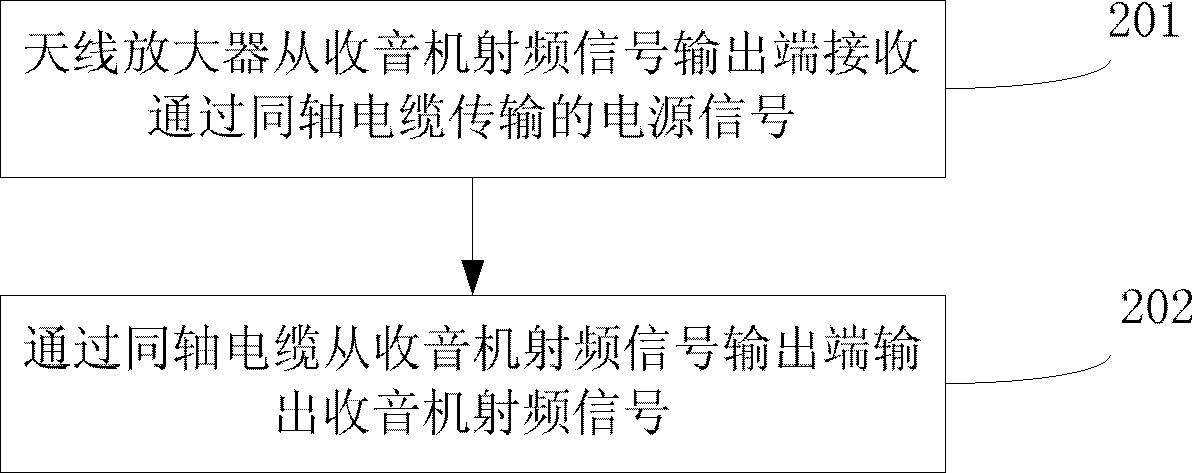
[0028] This embodiment provides a transmission method of a power signal and a radio frequency signal, see figure 2 , the method flow is as follows:

[0029] 201: The antenna amplifier receives the power signal transmitted through the coaxial cable from the radio frequency signal output end;

[0030] 202: Output radio frequency signals from the radio frequency signal output end through the coaxial cable.

[0031] Preferably, before outputting the radio frequency signal from the radio frequency signal output terminal through the coaxial cable, it also includes:

[0032] Filters radio frequency signals transmitted over coaxial cables.

[0033] Specifically, the radio frequency signal transmitted on the coaxial cable is filtered, specifically including:

[0034] The radio frequency signal transmitted on the coaxial cable is filtered by a filter circuit composed of a double diode and an inductor.

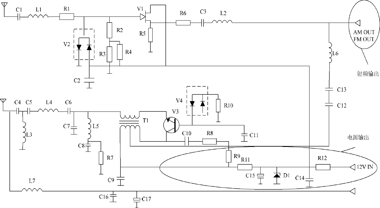
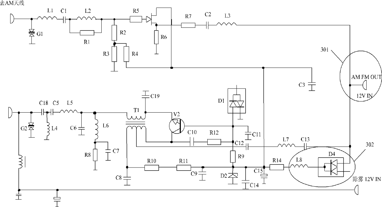
[0035] Specifically, see image 3 The transmission circuit diagram of the powe...

Embodiment 2

[0039] This embodiment provides an antenna amplifier, see Figure 4 , the antenna amplifier includes: a radio frequency signal output terminal 401 and a coaxial cable 402;

[0040] The radio frequency signal output terminal 401 is used to receive the power signal transmitted through the coaxial cable 402, and output the radio frequency signal through the coaxial cable 402;

[0041] The coaxial cable 402 is used for transmitting power signals and radio frequency signals.

[0042] Preferably, see Figure 5 , the antenna amplifier, also includes:

[0043] The filter 403 is used for filtering the radio frequency signal transmitted on the coaxial cable 402 .

[0044] Specifically, the filter 403 is specifically used to filter the radio frequency signal transmitted on the coaxial cable 402 through a filter circuit composed of dual diodes and an inductor.

[0045] combine image 3 The transmission circuit diagram of the power signal and the radio frequency signal is shown, where...


PUM


Abstract

The invention discloses a transmission method for power supply signals and radiogram radio-frequency signals as well as an antenna amplifier, belonging to the field of automobile antennas. The transmission method comprises the following steps: the antenna amplifier receives the power supply signals transmitted through a coaxial cable from an output end of the radiogram radio-frequency signals, and outputs the radiogram radio-frequency signals through the coaxial cable from the output end of the radiogram radio-frequency signals. The antenna amplifier comprises the output end of the radiogram radio-frequency signals and the coaxial cable. According to the transmission method for the power supply signals and the radiogram radio-frequency signals as well as the antenna amplifier, disclosed by the invention, the power supply signals and the radiogram radio-frequency signals are transmitted through the coaxial cable, thus a power line of the antenna amplifier of an automobile can be saved, and the purpose of saving arrangement of wires is realized; in addition, the radiogram radio-frequency signals transmitted through the coaxial cable are filtered, thus the interference on the radiogram radio-frequency signals further can be prevented, and the quality of the radiogram radio-frequency signals is ensured.

Description

technical field [0001] The invention relates to the field of automobile antennas, in particular to a method for transmitting power signals and radio frequency signals and an antenna amplifier. Background technique [0002] With the rapid development of the automobile industry, automobiles have more and more functions. Antenna amplifiers and radios are commonly used in various automobile products. While bringing people a comfortable experience, they also bring people A lot of convenience. [0003] For car antenna amplifiers that receive radio frequency signals, such as figure 1 The transmission circuit diagram of the power signal and the radio frequency signal in the prior art is shown. The radio frequency signal is output from the antenna amplifier through the coaxial cable, and the power signal is input into the antenna amplifier through a common wire to supply power for the antenna amplifier. [0004] In the process of realizing the present invention, the inventor finds ...

Claims


Application Information

Patent Timeline
Patent Type & Authority Patents(China)
IPC IPC(8): H04B1/16H03F3/19H04B1/10
Inventor 王俊王红余杨宁
Owner CHERY AUTOMOBILE CO LTD
Why Eureka
Try Eureka