
Tracheal cannula fixing article used after tracheotomy

A tracheal tube and tracheotomy technology, which is applied in the field of medical devices, can solve the problems of increasing the difficulty and mortality of critically ill patients, increasing the workload of medical staff, and increasing the risk of accidental tube detachment, so as to reduce neck skin or wounds. Injury and infection risk, pain relief and medical staff workload reduction, and the effect of reducing the chance of accidental dislodgement

Inactive Publication Date: 2012-05-02
SECOND MILITARY MEDICAL UNIV OF THE PEOPLES LIBERATION ARMY
View PDF4 Cites 1 Cited by
  • Summary
  • Abstract
  • Description
  • Claims
  • Application Information

AI Technical Summary

Benefits of technology

This technology helps keep an airway tube fixed during surgery without causing damage from pulling on it with sharp instruments like screwdrivers that may cause accidents such as dislodgment. It also makes replacing tubes faster than traditional methods while reducing chances for complications associated therewith.

Problems solved by technology

There currently exist technical problem addressed in this patents that involve improving the efficiency and safety of securing tracheals after surgery while minimizing injury risks associated with current techniques such as threaded sutures and clipping fiber tubes. Current solutions require multiple steps involving several tools like twist grippers and tackles, leading to increased complexity and potential hazards. Additionally, existing devices have poor usable areas where they may stick into the body when removing them once worn off.

Method used


Image

  • Tracheal cannula fixing article used after tracheotomy
  • Tracheal cannula fixing article used after tracheotomy
  • Tracheal cannula fixing article used after tracheotomy

Examples


Embodiment 1

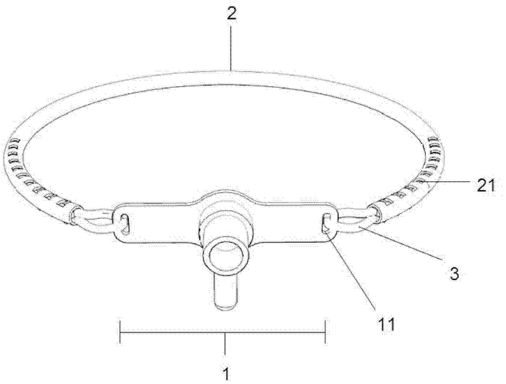
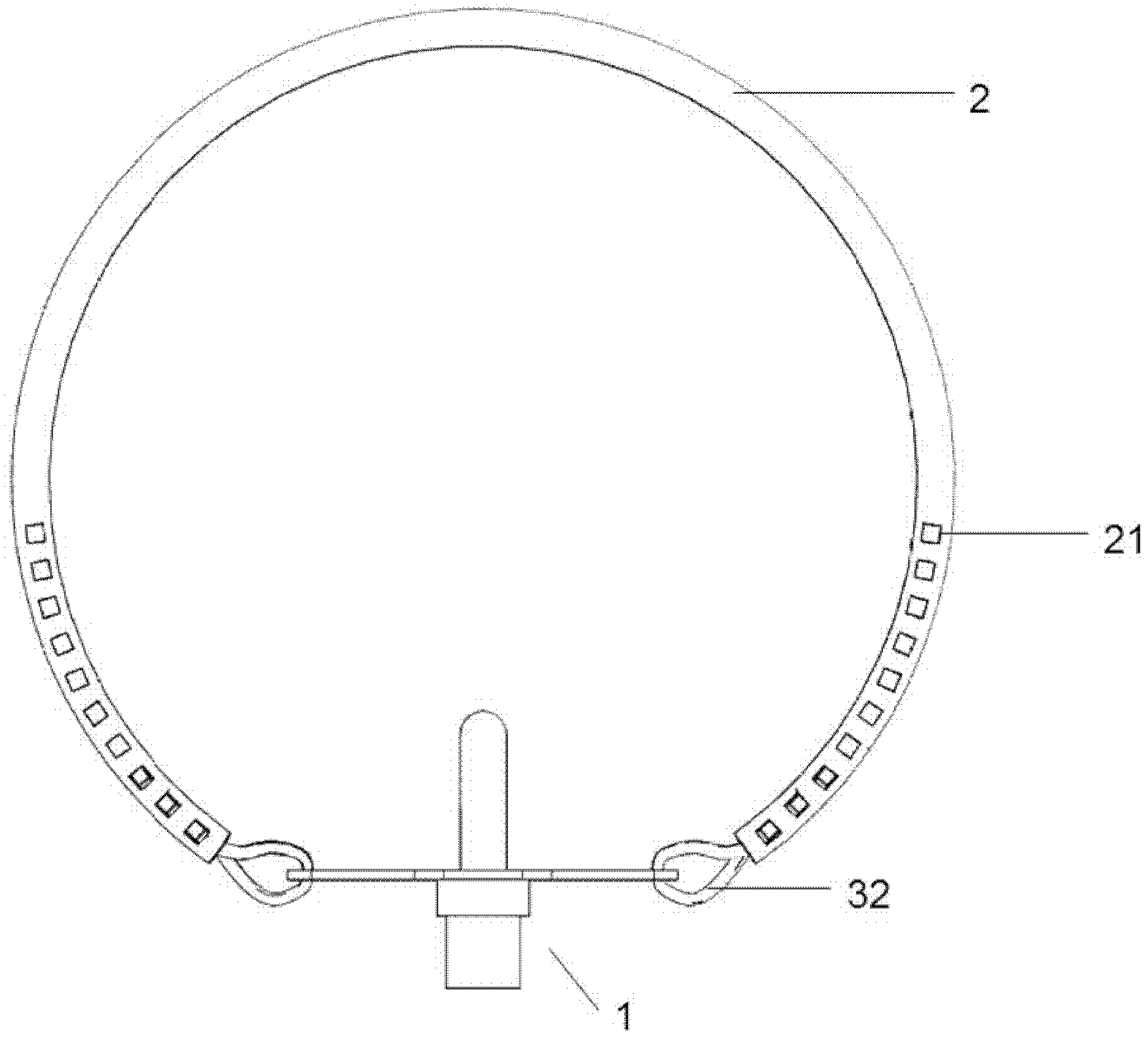
[0022] A tracheal tube fixation article after tracheotomy, such as figure 1 with 2 As shown, it is composed of a hollow trachea tube fixing rope 2 with locks 21 on both ends of the tube wall and two self-locking devices 3. The locks 21 are square, and the number of locks 21 is the number of tubes at each end. 10 on the wall.

[0023] The lock 21 can be tightly locked with the self-locking device 3 , and the self-locking device 3 is connected with the tracheal tube fixing hole 11 on the tracheal tube 1 .

[0024] The tracheal cannula can be selected from the 6#-8# tracheal cannula of Mallinckrodt Company of the United States or RUSCH Company of Germany.

Embodiment 2

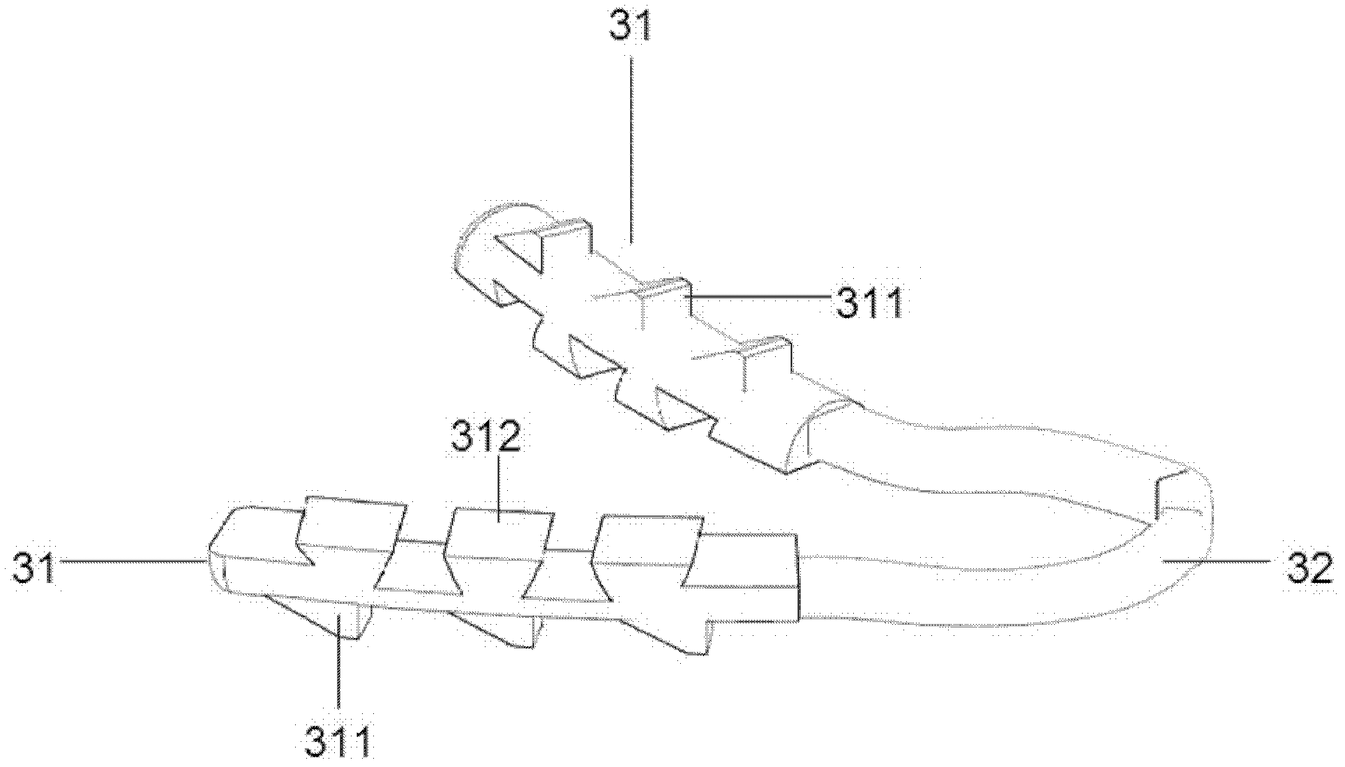
[0026] A tracheotomy postoperative tracheal tube fixation article is based on the structure of embodiment 1, wherein the number of locks 21 is 6 on the tube wall at each end; wherein the self-locking device 3 is as follows: Figures 2 to 5 As shown, the self-locking device 3 is composed of a connecting part 32 in the middle and self-locking ends 31 at both ends. The two self-locking ends 31 lock each other and fix them into a cylindrical whole through the inner trapezoidal self-locking teeth 312 of the inner self-locking ends. , and then the trapezoidal locking teeth 311 outside the cylindrical outer side of the self-locking end are tightly locked with the lock buckles 21 on the pipe walls at both ends of the tracheal tube fixing rope 2; the inner trapezoidal self-locking teeth 312 of the self-locking end and the outer side The number of trapezoidal locking teeth 311 is three.

[0027] In clinical use, first pass through the tracheal tube fixing hole 11 with two self-locking d...


PUM


Abstract

The invention relates to the technical field of medical instruments. In the widely-applied clinical method for cutting the tracheal cannula of a patient with a fixed trachea, a cotton rope, a cotton strip or gauze is knotted on tracheal cannula fixing hole(s) at one end or two ends for fixing the tracheal cannula on the neck part. The invention aims to provide a tracheal cannula fixing article used after tracheotomy, which can be replaced quickly without knotting. The fixing article consists of a hollow tracheal cannula fixing rope (2) of which the pipe walls at the two ends are provided with lock catches, and two self-locking devices (3). When the tracheal cannula fixing article is in use, residual parts at the two ends of the tracheal cannula fixing rope are cut off in comparison to the practical neck circumference, the self-locking devices pass through the tracheal cannula fixing hole(s), self-locking ends are enclosed, and the enclosed self-locking ends are inserted into the two ends of the hollow tracheal cannula fixing rope and is buckled with the lock catches on the pipe walls. By adopting the tracheal cannula fixing article, the accidental falling probability of the tracheal cannula and the neck skin or wound damage and infection risks of the patient are lowered, and the pain of the patient and the workload of medical personnel are lowered.

Description


Claims


Application Information

Patent Timeline
Owner SECOND MILITARY MEDICAL UNIV OF THE PEOPLES LIBERATION ARMY
Learn More