
LED lamp

一种发光二极管、灯具的技术,应用在发光元件的半导体器件、光源、电光源等方向,能够解决不利灯具寿命与稳定性、灯具体积的欲小不易、增加支撑与荷重负担等问题,达到提升安装与维修效率、延伸照明容量、降低拆装与维修成本的效果

Inactive Publication Date: 2012-05-16
FU ZHUN PRECISION IND SHENZHEN +1
View PDF4 Cites 6 Cited by
  • Summary
  • Abstract
  • Description
  • Claims
  • Application Information

AI Technical Summary

Problems solved by technology

However, the above-mentioned lighting devices that use natural circulation to dissipate heat generally reduce the light efficiency and easily lead to light decay due to overheating of the LEDs, which is not conducive to the life and stability of the lamps.
And because of the overweight of the radiator and the small size of the lamp, it is not easy to increase the burden of support and load
It is also because multiple people need to work together to install the high-altitude lamps through the elevator, and even if there is a minor fault during use, the same equipment and manpower carrying tools need to be used to remove the entire lamp at high altitude and then replace the entire lamp. In addition to greatly increasing the maintenance cost of on-site disassembly and restoration of normal lighting, the efficiency is also greatly reduced
Furthermore, the versatility of general lighting devices is low. In order to meet different lighting applications and customer needs, lamps with different types and appearances must be redesigned and manufactured, resulting in waste of resources, increased costs and greatly reduced operating efficiency.

Method used


Image

  • LED lamp
  • LED lamp
  • LED lamp

Examples


Embodiment Construction

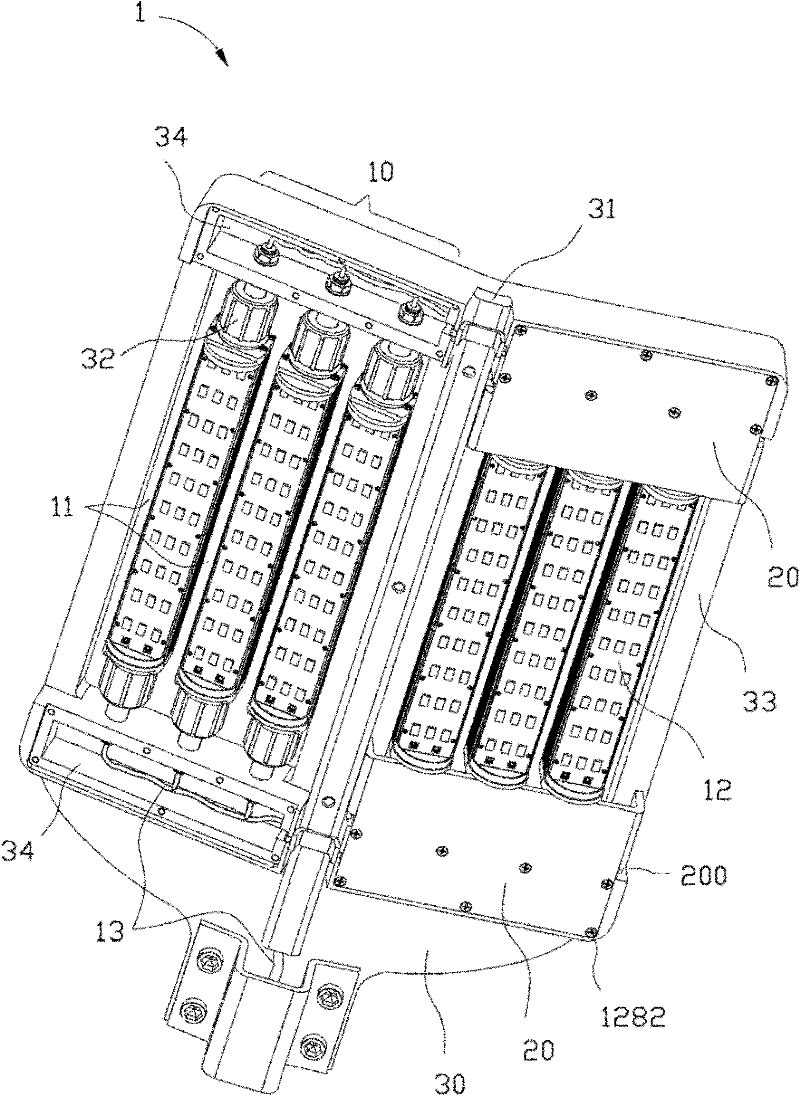
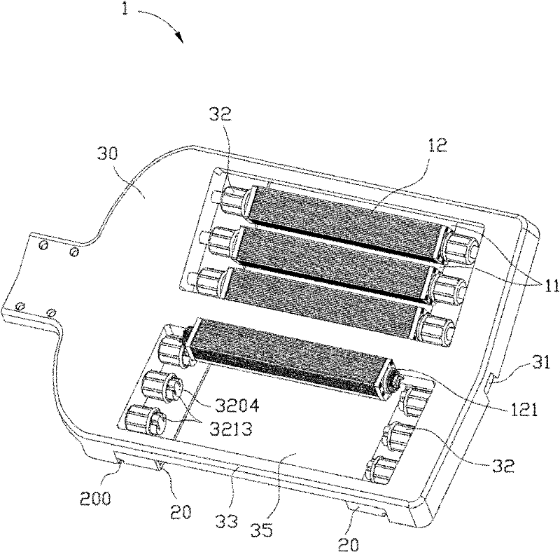
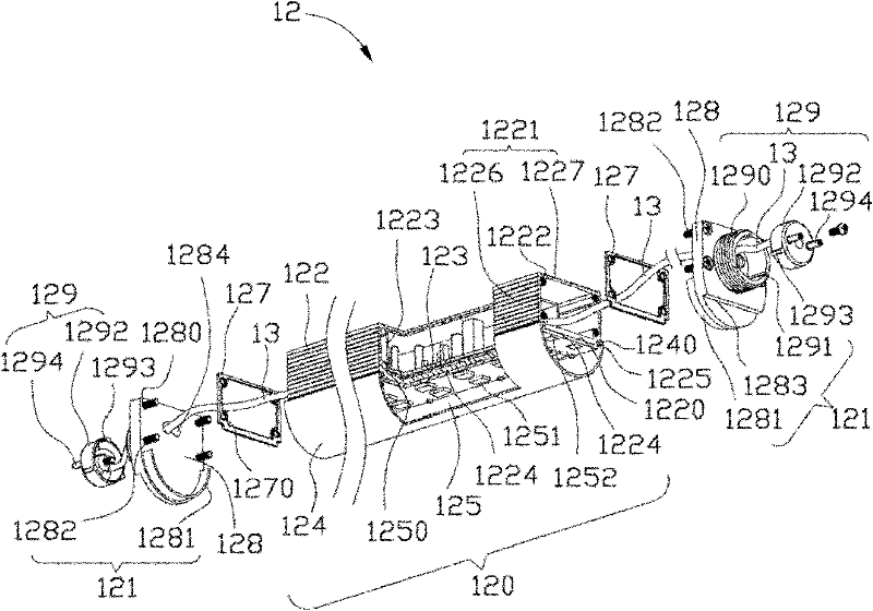
[0112] Refer to the following Figure 1 to Figure 12 , to further illustrate the light-emitting diode lamp 1 of the present invention.

[0113] figure 1 It is a three-dimensional assembled bottom view of the first embodiment of the light-emitting diode lamp 1 of the present invention (part of the supporting plate 20 is not shown), figure 2 yes figure 1 A three-dimensional top view of disassembling and assembling the lighting unit 12 (part of the lighting unit 12 is not shown), image 3 yes figure 1 A partial cross-sectional view of the lamp tube module 120 of the middle lighting unit 12 and a three-dimensional exploded view of the front and rear end joints 121, Figure 4 yes figure 1 The three-dimensional exploded view of the first connection terminal 32 and the connection relationship diagram with the trunking 34 and the lighting unit 12, Figure 5 yes Figure 4 The three-dimensional exploded view of the middle socket 321, Image 6 yes figure 1 The three-dimensional...


PUM


Abstract

The invention provides an LED lamp, which comprises a lamp panel, a plurality of first wiring terminals and a plurality of lighting modules, wherein the lamp panel is provided with a plurality of openings, and each lighting module is arranged on each opening; the first wiring terminals are respectively arranged on at least one inner side wall of each opening at intervals and electrically connected with an external power supply; each lighting module comprises a plurality of lighting units, wherein each lighting unit comprises a hollow heat dissipating member, a circuit board and a light source module arranged on the heat dissipating member; each of the two ends of each lighting unit is respectively provided with a joint member and the joint members are arranged on the inner side walls of the openings at intervals in a sealing way; and the circuit board of each lighting unit is used for supplying power to the light source modules through second wiring terminals which are arranged on at least one joint member and electrically connected with the first wiring terminals.

Description

technical field [0001] The invention relates to a light-emitting diode lamp, in particular to a modularized light-emitting diode lamp with high heat dissipation efficiency. Background technique [0002] Traditional lighting sources consume a lot of energy, while Light Emitting Diode (LED) has the advantages of high light efficiency, energy saving, long life, environmental protection (mercury-free), fast start-up, strong light directionality, shock resistance and impact resistance, etc. It has the potential to widely replace traditional lighting sources. [0003] However, the use of LEDs in lighting devices must cooperate with a high-efficiency heat dissipation mechanism to reduce the temperature of the LEDs in order to exert the above-mentioned advantages. Otherwise, the luminous efficiency and service life of the LED will be greatly reduced, and the impact will make the lighting device using the LED less effective in energy saving, and directly impact the reliability of th...

Claims


Application Information

Patent Timeline
Patent Type & Authority Applications(China)
IPC IPC(8): F21S8/00F21V17/12F21V19/00F21V23/06F21V29/00F21V31/00F21Y101/02
CPCF21V15/011F21V23/023F21Y2105/001F21V15/015F21V31/005F21S2/005F21V23/008F21V23/001F21V23/06F21Y2101/02F21W2131/103F21V23/005F21Y2113/00F21V29/507F21Y2105/10F21Y2115/10F21V23/006F21K9/278
Inventor 刘泰健
Owner FU ZHUN PRECISION IND SHENZHEN
Learn More