Vacuum kneading-and-defoaming device

一种混揉、脱泡的技术,应用在混合机、液体脱气、运输和包装等方向,能够解决脱泡不充分等问题,达到提高作业效率、避免品质降低的效果

Active Publication Date: 2012-05-23
马康
View PDF5 Cites 9 Cited by
  • Summary
  • Abstract
  • Description
  • Claims
  • Application Information

AI Technical Summary

Problems solved by technology

[0012] However, after the paste material is accommodated in a closed syringe-shaped container, for example, in a syringe-shaped container, a decompressed state is carried out in a kneading and degassing device of a structure for kneading and degassing the paste material, During the operation of the device, since the gas discharged into the syringe-shaped container cannot be discharged to the outside of the syringe-shaped container by the degassing action, bubbles remain in the paste material after the treatment, that is, there is insufficient degassing. The problem

Method used


Image

  • Vacuum kneading-and-defoaming device
  • Vacuum kneading-and-defoaming device
  • Vacuum kneading-and-defoaming device

Examples


no. 1 approach

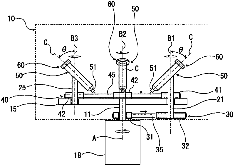
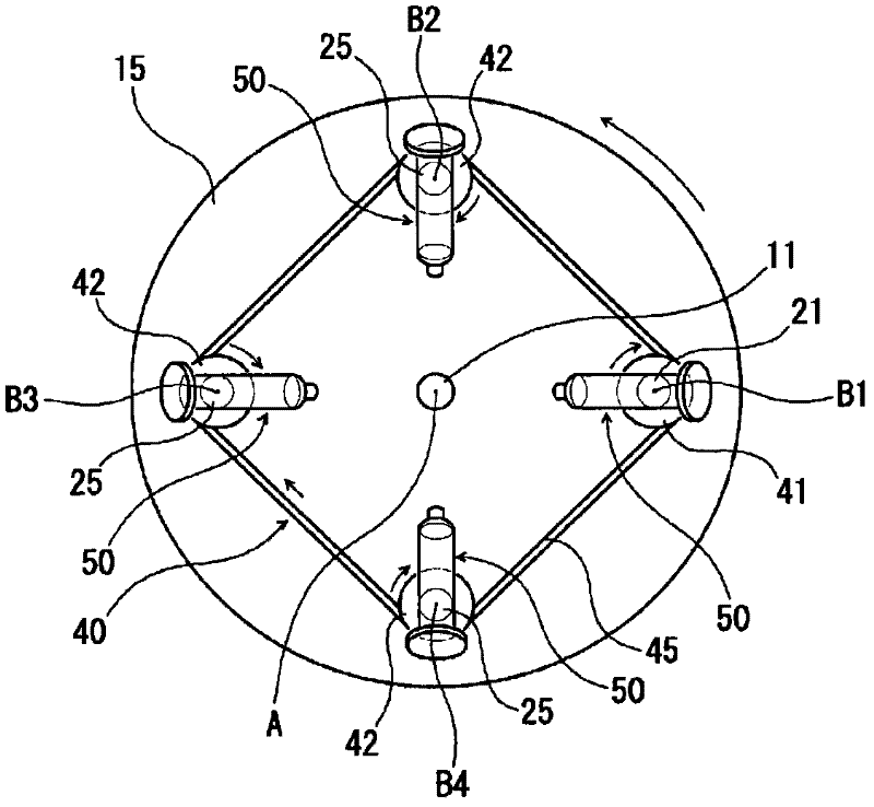
[0034] figure 1 It is an explanatory cross-sectional view showing an outline of a basic structure in an example of the vacuum kneading and defoaming device according to the first embodiment of the present invention, figure 2 is viewed from the vertical direction above figure 1 The top view of the vacuum kneading and defoaming device shown.

[0035] This vacuum kneading and defoaming device is provided with: a cylindrical chamber 10 forming a closed space inside; The driving motor 18 of the driving rotating shaft body 11 for the revolution of the drive; the disc-shaped rotating plate 15 for revolution rotating in the horizontal plane centered on the reference driving rotating shaft A; The rotating center axis extending parallel to the axis A is the operating rotating shaft body 21 for autorotation, which is provided to rotate freely; A plurality of self-rotating driven rotating shafts 25 provided freely in the center; an operating rotating shaft driving mechanism 30 for rot...

no. 2 approach

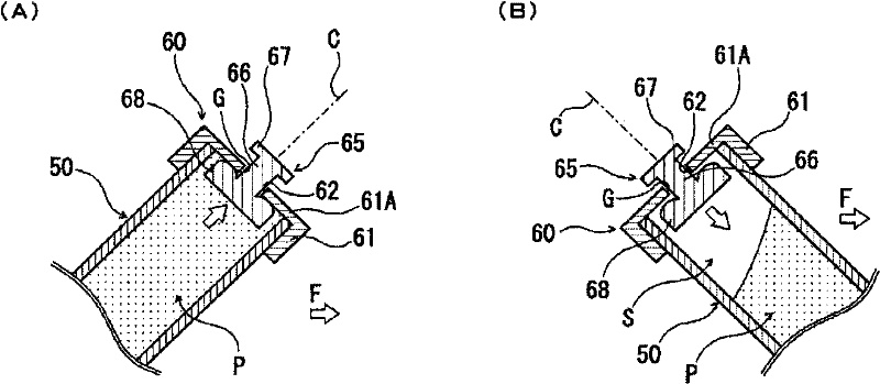
[0061] The vacuum kneading and degassing device of the second embodiment of the present invention uses the following structure: as the syringe-shaped container 50, an opening on one end side for filling the paste material P into the syringe-shaped container 50 is provided with a Cover member 70 for exhaust function.

[0062] Cover part 70, such as Figure 5 (A) and Figure 5 As shown in (B), a bottomed cylindrical holder that is detachably mounted on the opening of the one end side of the syringe-shaped container 50 so as to accommodate one end of the syringe-shaped container 50 and block the opening of the syringe-shaped container 50 The frame 61 and the gas permeable membrane 75 that does not permeate the paste material are provided on the inner surface of the end wall 61A of the holder 61 so as to cover the through hole 62 formed in the center of the end wall 61A.

[0063] The gas permeable membrane 75 is, for example, a film-like membrane having the properties of prevent...


PUM


Abstract

Provided is a vacuum kneading-and-defoaming device that can subject a paste material contained in a cylindrical paste container to uniform and sufficient kneading and to sufficient and highly efficient defoaming. The disclosed vacuum kneading-and-defoaming device includes: a revolution-purpose rotary element that is provided inside a chamber to be brought into a decompressed state, and that rotates within a horizontal plane about a reference drive rotation axis; a container retaining means that is provided on the orbiting edge of the revolution-purpose rotary element in a manner so as to be spinnable about an operation rotation axis which is parallel to the reference drive rotation axis, and that detachably retains a paste container in a state such that the central axis of the paste container obliquely intersects with the operation rotation axis; and a drive mechanism that rotates the revolution-purpose rotary element and the container retaining means. An opening provided in the paste container for the introduction of a paste material has: a degassing valve that opens the interior space of the paste container to the interior space of the chamber by the action of centrifugal force caused by the revolution and the spinning of the paste container; or a gas-permeable membrane that is impermeable to the paste material.

Description

technical field [0001] The invention relates to a vacuum kneading and defoaming device. Background technique [0002] For example, medical paste materials such as paste materials used as sealants for liquid crystals and semiconductor elements, conductor paste materials, resistor paste materials, or compound pastes for rubbing medicines need to be fully kneaded, It is used in a defoamed state. In such a paste material, for example, at least two or more liquids with high viscosity and different specific gravity values, or liquids and powders with different specific gravity are required to be uniformly mixed and dispersed. [0003] Currently, various types of kneading and defoaming devices for kneading and defoaming paste materials have been proposed. For example, someone has proposed a scheme of the following structure: the container holding body, for example, a cup-shaped paste container that holds the paste material to be kneaded in a detachable manner, revolves around a re...

Claims


Application Information

Patent Timeline
Patent Type & Authority Applications(China)
IPC IPC(8): B01D19/00B01F9/22B01F29/90
CPCB01F9/0001B01L3/50825B01D19/0047B01F13/06B01F15/00993B01D19/0052B01L2400/06B01D19/0031B01F9/0025B01L3/5021B01D19/0026B01F9/0014B29B7/106B29B7/845B01F29/10B01F29/331B01F33/70B01D19/00B01F29/90
Inventor 原田学
Owner 马康
Why Eureka
Try Eureka