
Locomotive tread unit brake with constant braking force

A braking force and brake technology, applied in the direction of brakes with brake parts, railway braking system, railway car body parts, etc., can solve the problem that the output of braking force cannot be guaranteed

Inactive Publication Date: 2012-06-20
CRRC DALIAN CO LTD
View PDF5 Cites 4 Cited by
  • Summary
  • Abstract
  • Description
  • Claims
  • Application Information

AI Technical Summary

Problems solved by technology

As a result, when the enlarged cam is in different working positions, the braking ratio also changes at the same time, and the braking force will inevitably fluctuate within a certain range, which cannot guarantee a constant braking force output.

Method used


Image

  • Locomotive tread unit brake with constant braking force
  • Locomotive tread unit brake with constant braking force
  • Locomotive tread unit brake with constant braking force

Examples


Embodiment Construction

[0010] In order to make the purpose, technical solutions and advantages of the embodiments of the present invention clearer, the technical solutions in the embodiments of the present invention will be clearly and completely described below in conjunction with the drawings in the embodiments of the present invention. Obviously, the described embodiments It is a part of embodiments of the present invention, but not all embodiments. Based on the embodiments of the present invention, all other embodiments obtained by persons of ordinary skill in the art without creative efforts fall within the protection scope of the present invention.

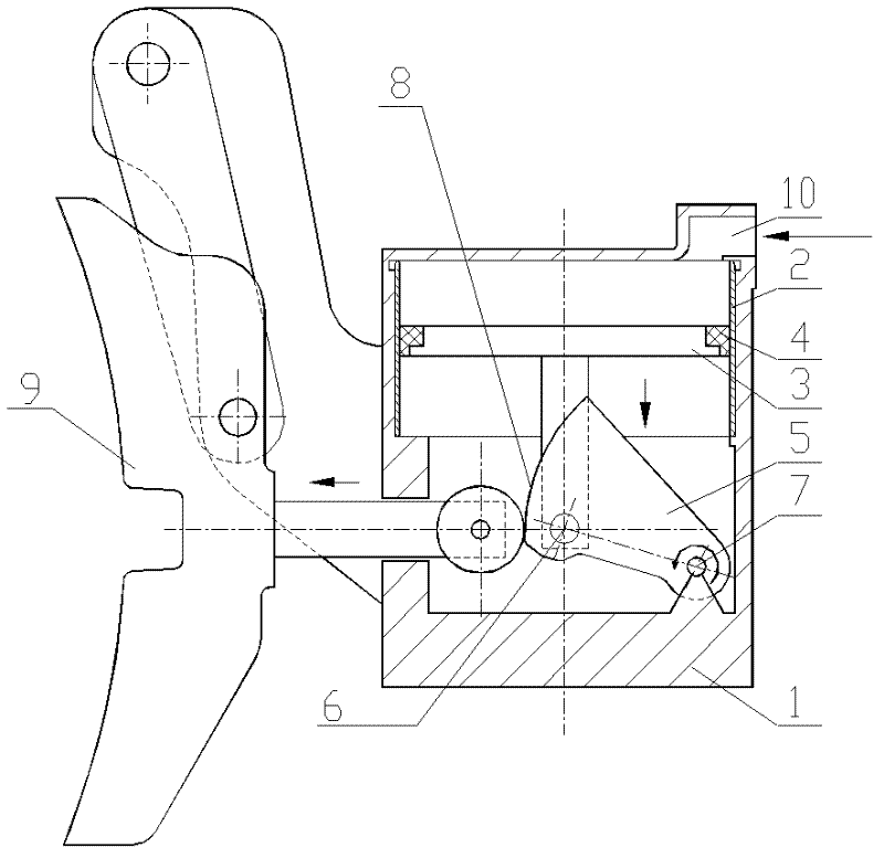
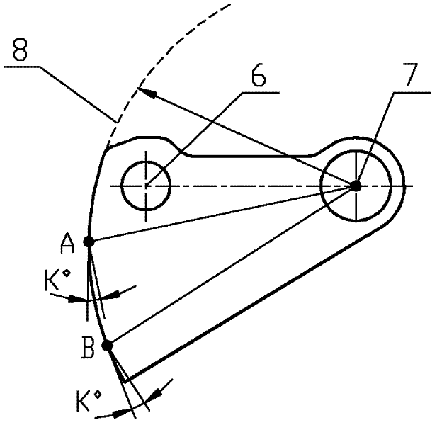
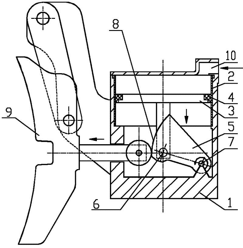
[0011] See attached figure 1 . The constant braking force locomotive tread unit brake of this example is composed of a brake shoe force transmission mechanism (9) and a sealed pressure working chamber (1). A bushing (2), a brake pad (3) and a paddle cup (4) are arranged in the brake cylinder body of the sealed pressure working chamber (1). Wher...


PUM


Abstract

The invention discloses a locomotive tread unit brake with constant braking force, comprising a brake shoe force transmission mechanism (9), a brake cylinder (1), a bush (2), a brake piston (3) and a piston leather cup (4) which jointly form a sealed pressure working cavity. The front end of a magnifying cam (5) is hinged with a lower end (6) of the brake piston, the rear end of the magnifying cam (5) is hinged with a hinge point (7) of the brake cylinder, a working curved surface (8) of the magnifying cam (5) is a logarithmic spiral adopting the hinge point (7) of the brake cylinder as the origin of coordinates. Any point on a curve of the logarithmic spiral has a unique pressure angle, and accordingly a unique braking leverage is realized. Accordingly, constant braking force is assuredly outputted by the magnifying cam (5) when the magnifying cam (5) operates at any positions.

Description

technical field [0001] The invention relates to railway locomotive technology, in particular to a constant braking force locomotive tread unit brake. Background technique [0002] The locomotive tread unit brake is a basic braking device used for locomotive wheel tread braking with compressed air as the power source. Applications. A typical locomotive tread unit brake structure is a sealed pressure working chamber formed by a brake cylinder block, a bushing, a brake disc and a disc cup, and the initial braking force can be generated on the brake disc by filling compressed air. . The amplifying cam is an amplifying element of braking force, and its front end is hinged with the lower end of the brake lever, and its rear end is hinged with the brake cylinder. The working surface of the enlarged cam is an eccentric circle relative to the hinge point of the cam and the brake cylinder, and its shape parameters determine the braking ratio of the brake (that is, the proportional ...

Claims


Application Information

Patent Timeline
IPC IPC(8): B61H1/00
Inventor 王国明王卓敏王旭东杨怀军高峰
Owner CRRC DALIAN CO LTD
Learn More