
Method for monitoring power generation of oil engine at location of communication base station

A communication base station and oil generator technology, applied in wireless communication, electrical components, sustainable communication technology, etc., can solve problems such as unfavorable power generation time and cost, over-reported power generation time, error-prone, etc., to improve real-time monitoring of oil generator power generation The ability to improve communication support and prevent cheating in power generation

Active Publication Date: 2015-05-20
GOSUNCN TECH GRP
View PDF8 Cites 0 Cited by
  • Summary
  • Abstract
  • Description
  • Claims
  • Application Information

AI Technical Summary

Problems solved by technology

At present, communication operators know the power generation status through telephone notifications from power generation maintenance personnel, and manually record and verify the effectiveness of power generation. This method is difficult to grasp the power generation process of maintenance personnel in real time, and maintenance personnel are prone to falsely report power generation and overreport The duration of power generation; in addition, manually recording and verifying the effectiveness of power generation consumes a lot of manpower and is prone to errors, which is not conducive to counting the duration and cost of power generation
At present, communication operators have no effective way to monitor and manage the power generation process of maintenance personnel

Method used


Image

  • Method for monitoring power generation of oil engine at location of communication base station
  • Method for monitoring power generation of oil engine at location of communication base station

Examples


Embodiment Construction

[0023] The present invention will be described in detail below in conjunction with the embodiments and accompanying drawings.

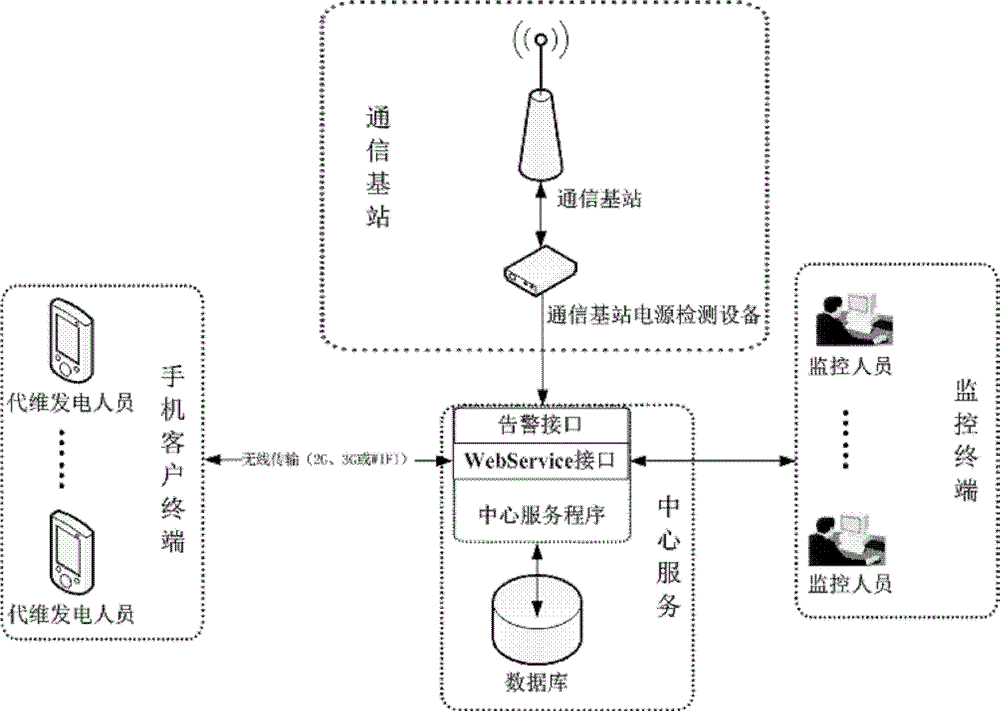
[0024] Such as figure 1 As shown, the monitoring system of the present invention mainly includes: a mobile phone client, a central service, a communication base station power detection device and a monitoring terminal.

[0025] The mobile phone client includes client programs running on various mobile phone operating system platforms. This program supports regular collection of latitude and longitude information of the mobile phone, and sends the geographic location information to the central service. When the power generation starts and ends, the power generation personnel report the power generation start and power generation end time through the mobile client program, and the central service automatically records the power generation report time and the geographical location information of the power generation personnel.

[0026] The central servi...


PUM


Abstract

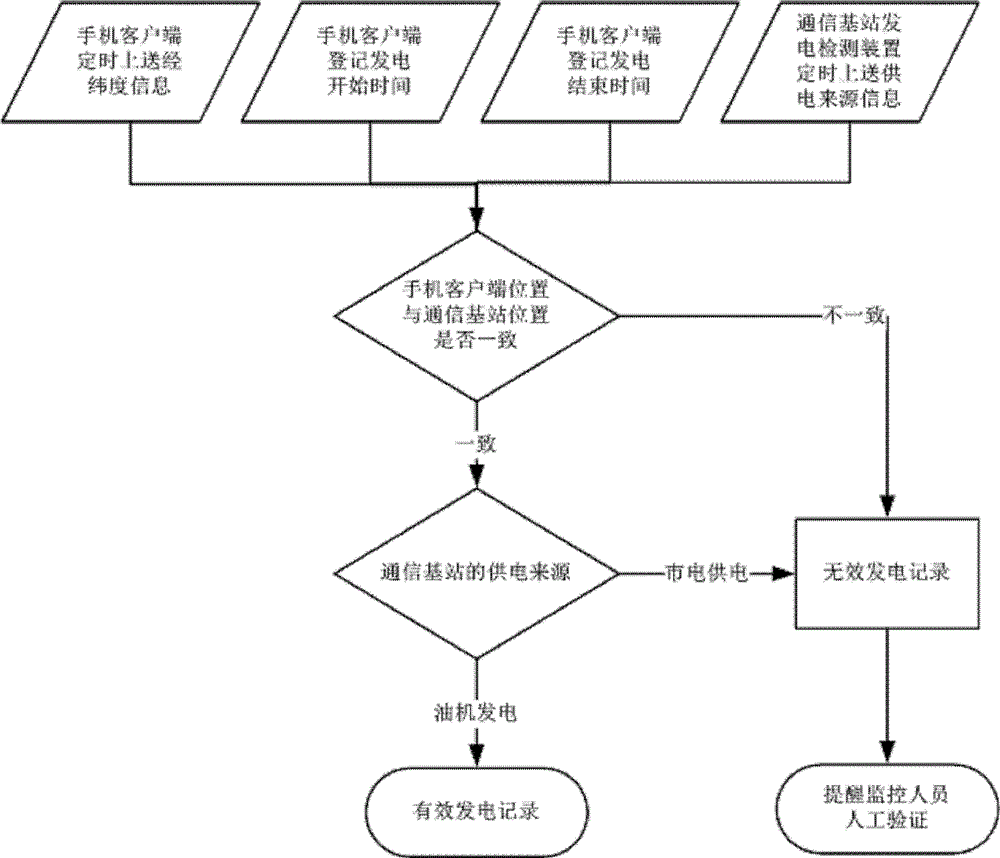
The invention relates to a method for monitoring power generation of an oil engine at the location of a communication base station. A mobile phone client uploads longitude and latitude information of the location of a mobile phone and submits power generation starting time and ending time to a central server; the central server judges whether the longitude and latitude information of the mobile phone client is consistent with the longitude and latitude information of the communication base station or not; if not, power generation personnel is deemed to be not on the power generation site of the communication base station, a power generation record at the time is deemed to be an ineffective power generation record and monitoring personnel is reminded to confirm; if so, the power generation record at the time is deemed to be preliminarily effective, whether the source of power supply to the communication base station is power generated by the oil engine or not is further judged, and if the source of the power supply to the communication base station is the power generated by the oil engine, the power generation record is effective; and if the source of the power supply to the communication base station is a normal mains power, the power generation record is ineffective and the monitoring personnel is reminded to confirm. By verifying the geographic location of the oil engine for power generation and the source of the power supply to the communication base station, the method can be used for effectively monitoring the power generation situation of the communication base station.

Description

technical field [0001] The invention relates to the field of operation and maintenance informatization in the communication industry, in particular to a monitoring method for monitoring the power generation of an oil generator where a communication base station is located. Background technique [0002] For the power outage guarantee of the communication base station, the communication operator manages the power generation through the personnel of the third-party maintenance company (hereinafter referred to as the "maintenance personnel"). How to efficiently monitor the power generation of maintenance personnel, accurately understand the power generation of communication base stations, and ensure timely recovery of communication at power outage base stations has always been an important problem that communication operators are difficult to solve. At present, communication operators know the power generation status through telephone notifications from power generation maintena...

Claims


Application Information

Patent Timeline
Patent Type & Authority Patents(China)
IPC IPC(8): H04W24/04
CPCY02D30/70
Inventor 刘炽明舒海燕宋保军
Owner GOSUNCN TECH GRP
Learn More