
Core wire supply apparatus and spinning machine having the same

A technology of supplying device and core thread, which is applied in the direction of continuous winding spinning machine, spinning machine, open-end spinning machine, etc. Effect

Active Publication Date: 2012-07-04
MURATA MASCH LTD
View PDF9 Cites 15 Cited by
  • Summary
  • Abstract
  • Description
  • Claims
  • Application Information

AI Technical Summary

Problems solved by technology

Therefore, when the suction device that pulls out the core wire from the core wire bobbin by the action of air and sends out the core wire is used as the core wire sending part, the air flow ejected from the suction device is strong, causing the supply Problems such as disorder of fiber bundles in the air spinning device
[0005] Such a problem, even if it is a core wire supply device equipped with a tension relaxation part (a mechanism that causes the core wire to relax) as shown in Japanese Patent Application Laid-Open No. 5-302225, due to the tension relaxation part and the core wire delivery part (suction device) ) is placed between the tension imparting part (tensioner), so it is not possible to make a big improvement

Method used

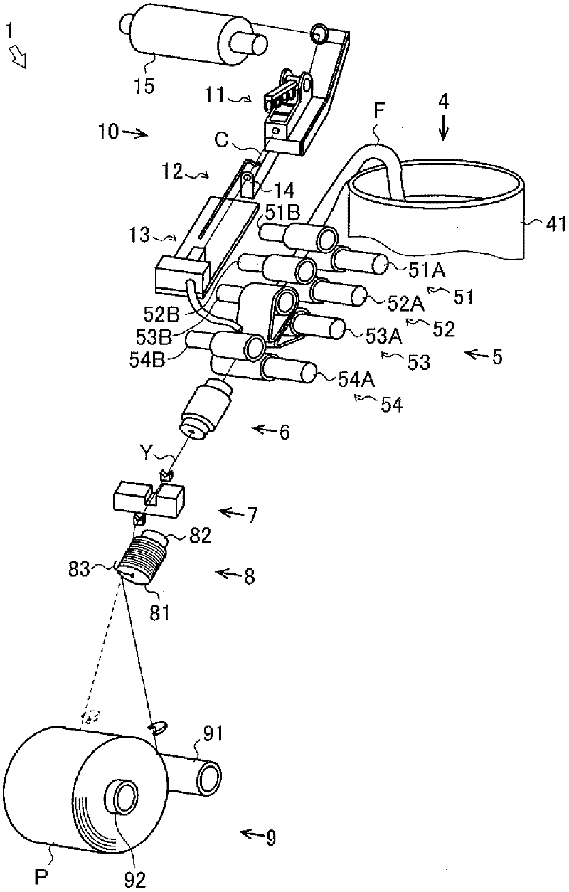
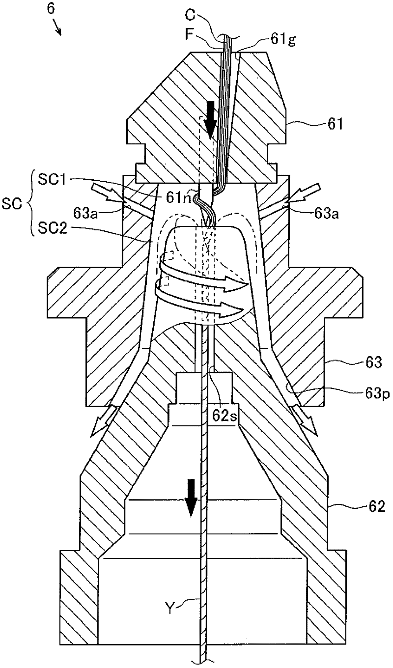
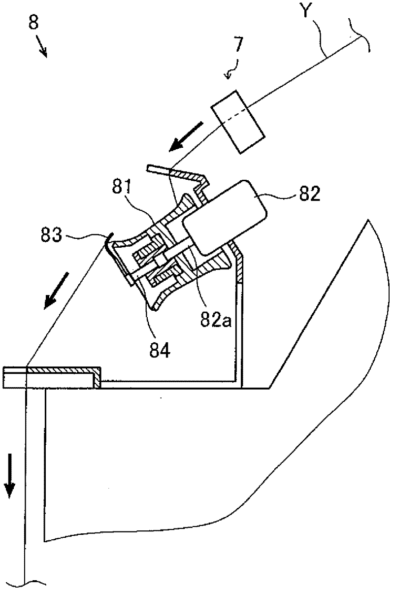

Image

  • Core wire supply apparatus and spinning machine having the same
  • Core wire supply apparatus and spinning machine having the same
  • Core wire supply apparatus and spinning machine having the same

Examples


Embodiment Construction

[0032] First, use figure 1 The overall structure of the spinning unit 1 will be described.

[0033] The spinning unit 1 is a spinning machine that manufactures a spun yarn Y from a core yarn C and a fiber bundle (hereinafter referred to as "sliver") to form a package P. The spinning unit 1 is mainly composed of a sliver supply unit 4 arranged along the conveying direction of the sliver F and the spinning yarn Y, a drafting device 5, an air spinning device 6, a yarn defect detection device 7, a tension stabilizing device 8 and a winding The device 9 constitutes. Furthermore, the spinning unit 1 is provided with a core yarn supply device 10 that supplies the core yarn C to the air spinning device 6 .

[0034] The sliver supply device 4 supplies the sliver F as a raw material of the spun yarn Y to the draft device 5 . The sliver supply device 4 is mainly composed of a sliver case 41 and a not-shown guide rail. The sliver F stored in the sliver housing 41 is guided by the cree...


PUM


Abstract

The invention provides a core wire supply apparatus capable of utilizing a core wire send-out portion to send out core wire and a spinning machine having the core wire supply apparatus. The core wire supply apparatus comprises a core wire send-out portion (13) for sending out the core wire (C) pulled out from a core wire bobbin (15), a tension giving portion (11) which is arranged between the core wire bobbin (15) and the core wire send-out portion (13) for giving tension to the above mentioned core wire (C), and a tension relaxing portion (12) which is arranged between the tension giving portion (11) and the core wire send-out portion (13) for making the tension of the above mentioned core wire (C) relaxed.

Description

technical field [0001] The present invention relates to the technology of a core yarn supply device and a spinning machine equipped with the core yarn supply device. Background technique [0002] Conventionally, there is known a spinning unit that manufactures a spun yarn by twisting fibers around a core yarn. Such a spinning unit is provided with an air spinning device and a core yarn supply device, wherein the air spinning device utilizes the swirling air of the air to twist the fiber, and the core yarn supply device supplies the core yarn to the air spinning device (for example, JP Kaiping No. 5-302225 Bulletin). [0003] The core wire supply device is provided with a core wire delivery part that pulls out the core wire from a core wire bobbin wound with the core wire and feeds out the core wire. In addition, the core thread supply device is provided with a tension applying unit that applies tension to the core thread pulled out from the core thread bobbin so that the c...

Claims


Application Information

Patent Timeline
Patent Type & Authority Applications(China)
IPC IPC(8): D01H1/20D01H13/10D01H4/00
Inventor 秋元理宏山本厚志
Owner MURATA MASCH LTD
Learn More