
Method for arranging energy-saving oven pipes

An arrangement method and oven technology, applied in lining repair and other directions, can solve the problems of unstable ignition, uneven temperature, ignition danger, etc., and achieve the effects of improving the heating rate control accuracy, good temperature uniformity, and improving utilization efficiency.

Inactive Publication Date: 2012-07-04
WISDRI WUHAN WIS IND FURNACE
View PDF5 Cites 0 Cited by
  • Summary
  • Abstract
  • Description
  • Claims
  • Application Information

AI Technical Summary

Problems solved by technology

[0002] Difficult ignition, unstable ignition and uneven temperature are the problems often encountered during the heating of the oven with low calorific value gas, especially gas with large calorific value or pressure fluctuations, resulting in frequent flameouts in the on-site oven, especially It is the initial heating stage that requires multiple ignitions
In response to this situation, the on-site oven personnel need to ignite multiple times, and a large amount of cotton yarn and gasoline are consumed during the ignition process, and some even throw a large amount of wood on site to support the combustion; at the same time, in this state, although the flame is turned off, the The gas is still in the supply state, which leads to waste of gas, and also makes the inside of the furnace full of gas, causing great danger to enter the furnace for ignition
[0003] At present, because it is believed that the oven tubes are only used in the oven stage, and the oven tubes in the furnace will be scrapped after the oven is finished, there is no organization to carry out targeted in-depth energy-saving improvements

Method used


Image

  • Method for arranging energy-saving oven pipes
  • Method for arranging energy-saving oven pipes
  • Method for arranging energy-saving oven pipes

Examples


Embodiment Construction

[0024] The design and layout of the new energy-saving oven tubes of the present invention, which can adapt to the large fluctuations in calorific value and pressure, will be described in detail below with reference to the accompanying drawings.

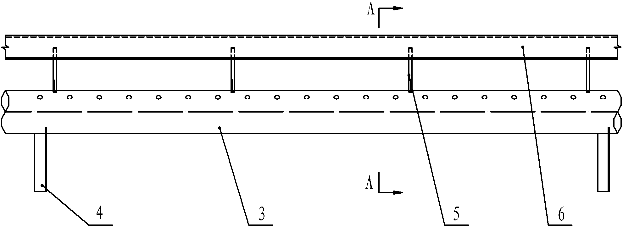
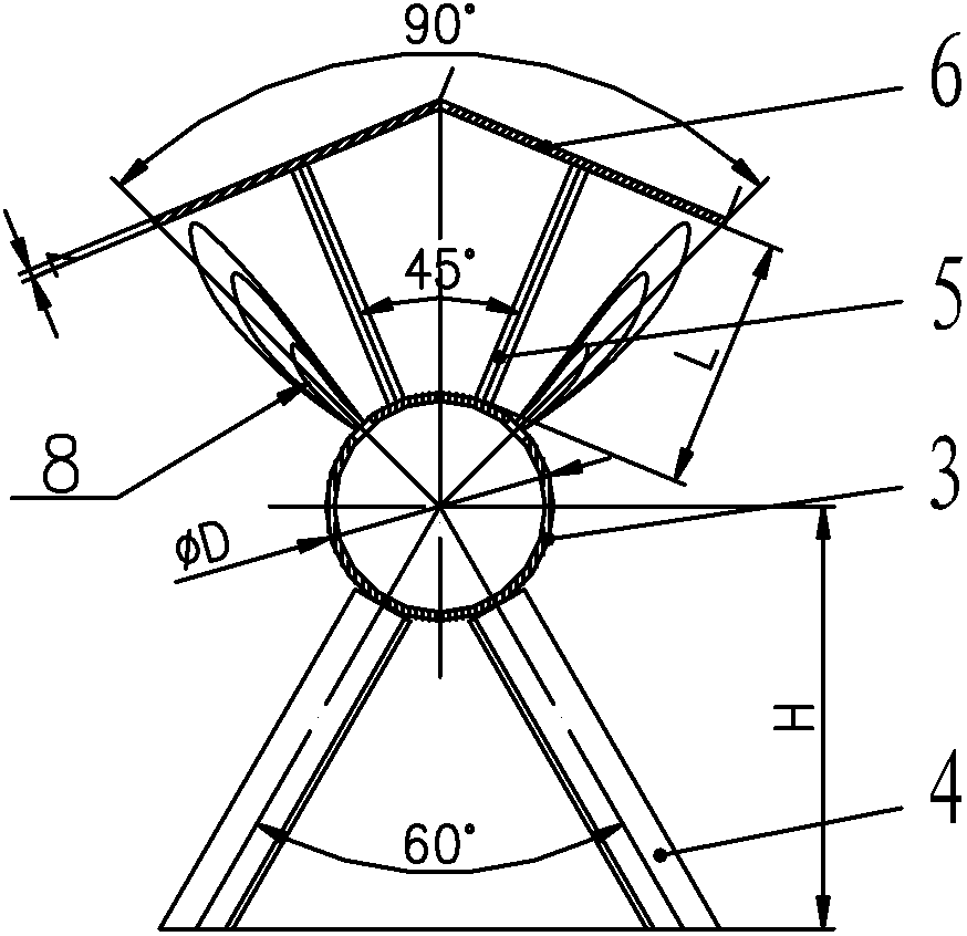
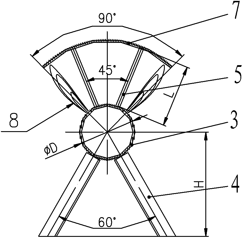
[0025] For the arrangement method of the energy-saving oven tube provided by the present invention, see Figure 5 , including the furnace tube installation process and laying process, as follows:

[0026] 1. Oven tube installation process:

[0027] When laying the cotton yarn 1, it is recommended to adopt the winding method, and to wind more cotton yarn at the position of the opening 2 of the oven tube. After winding and laying the cotton yarn 1 on the tube body of the oven tube 3, pour gasoline on the cotton yarn 1, and finally place the inverted V-shaped sheet cover 6 or the inverted U-shaped sheet cover 7 on the corresponding flame stabilizing device bracket of the oven tube 3 5 on.

[0028] When laying cotton yarn, the stable h...


PUM


Abstract

The invention provides a method for arranging energy-saving oven pipes, which includes the processes of oven pipe installation and oven pipe laying, wherein the process of oven pipe installation includes the steps of winding and laying spun cotton (1) on the pipe bodies of the oven pipes (3), pouring gasoline on the spun cotton, and finally placing a thin plate on a flame stabilizing device bracket (5) corresponding to the oven pipes; and the process of oven pipe laying process includes the steps of uniformly laying the energy-saving oven pipes at each section of the oven in the length direction, connecting the energy-saving oven pipes at the same section of the oven onto a fuel gas supply pipeline, and at side walls, introducing a pipeline to be connected with other oven pipes, eliminating the laying of the energy-saving oven pipes, and sealing and welding the connection parts of the energy-saving oven pipes. The method provided by the invention can effectively control the period of the oven, improves the control accuracy of the temperature increment rate, remarkably reduces the consumption of gasoline, spun cotton and the like, remarkably improves the operation intensity of the oven, greatly reduces the manual ignition frequency and improves the utilization efficiency of fuel gas, thereby saving manual labor, material resources and financial resources.

Description

technical field [0001] The invention relates to an oven tube, in particular to an arrangement method for an energy-saving oven tube used in gas supply conditions with low calorific value and large pressure fluctuations. Background technique [0002] Difficult ignition, unstable ignition and uneven temperature are the problems often encountered during the heating of the oven with low calorific value gas, especially gas with large calorific value or pressure fluctuations, resulting in frequent flameouts in the on-site oven, especially It is the initial heating stage that requires multiple ignitions. In response to this situation, the on-site oven personnel need to ignite multiple times, and a large amount of cotton yarn and gasoline are consumed during the ignition process, and some even throw a large amount of wood on site to support the combustion; at the same time, in this state, although the flame is turned off, the The gas is still in the state of supply, which causes th...

Claims


Application Information

Patent Timeline
Patent Type & Authority Applications(China)
IPC IPC(8): F27D1/16
Inventor 李卫杰张大宝
Owner WISDRI WUHAN WIS IND FURNACE
Learn More