Nozzle head

A technology of nozzle heads and nozzles, which is applied in the direction of spraying devices, spraying devices, optics, etc., and can solve problems such as dripping onto glass panels

Inactive Publication Date: 2012-07-04
TOP ENG CO LTD
View PDF6 Cites 5 Cited by
  • Summary
  • Abstract
  • Description
  • Claims
  • Application Information

AI Technical Summary

Problems solved by technology

In addition, during the process of using the nozzle head 220 to coat the liquid crystal on the glass panel, the liquid crystal remaining on the front end of the nozzle head 220 may drop onto the glass panel along with the subsequent liquid crystal droplets.

Method used


Image

  • Nozzle head
  • Nozzle head
  • Nozzle head

Examples


Embodiment Construction

[0029] Hereinafter, an embodiment of the present invention will be described in detail with reference to the accompanying drawings.

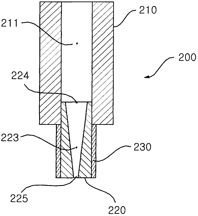
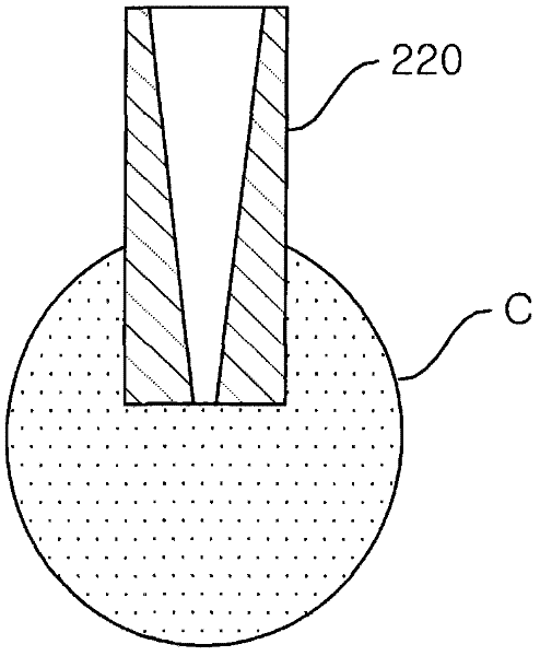
[0030] Figure 5 is a perspective view of a nozzle tip 320 according to an embodiment of the present invention. Figure 6 is a longitudinal sectional view of a nozzle 300 having a nozzle tip 320 according to an embodiment of the present invention. Figure 7 is a view showing the liquid crystal shape formed on the front end of the nozzle head 320 according to the embodiment of the present invention. In the following explanation, the term "front end" refers to a side where liquid crystal is discharged from the nozzle head 320 .

[0031] see Figure 5 and 6 , The nozzle head 320 according to the embodiment of the present invention includes a large area part 321 , a small area part 322 , a flow channel 333 and a liquid crystal diffusion preventing member 330 . The large area portion 321 has a predetermined front end area. The small-area portio...


PUM


Abstract

The invention provides a nozzle head applied to a liquid crystal coating machine, wherein the front end of the nozzle head is reduced in area. Therefore, the amount of liquid crystal remained on the front end of the nozzle head is reduced. The nozzle head comprises a large-area part with a predetermined area, and a small-area part, wherein the area of the front-end area is smaller than the area of the large-area part. A flow passage passes through the large-area part and the small-area part. The diameter of the flow passage is reduced from the inlet to the outlet thereof. A liquid crystal diffusion preventive member is arranged to surround the outer peripheral surface of the small-area part.

Description

technical field [0001] The present invention relates to a nozzle mounted to a liquid crystal coater for coating liquid crystal onto a glass panel during the manufacture of a liquid crystal display. Background technique [0002] A liquid crystal coater is a device that applies droplets of liquid crystal onto a glass panel during the manufacture of a flat panel display such as an LCD (Liquid Crystal Display). [0003] figure 1 It is a perspective view showing the structure of a typical liquid crystal coater. figure 2 It is a longitudinal sectional view of a conventional nozzle installed in a liquid crystal coater. image 3 is a view showing liquid crystal droplets formed on the front end of a conventional nozzle head having no liquid crystal diffusion preventing member. Figure 4 is a view showing liquid crystal droplets formed on the front end of a conventional nozzle head having a liquid crystal diffusion preventing member. [0004] In the following, reference will be m...

Claims


Application Information

Patent Timeline
IPC IPC(8): G02F1/1341B05B1/28B05B1/02
CPCB05C5/02B05C11/10G02F1/1303
Inventor 金熙根李承宰金埈煐
Owner TOP ENG CO LTD
Why Eureka
Try Eureka