
Force application mechanism for linkage and braking of motorcycle

A force application mechanism and technology for motorcycles, which are applied to bicycle brakes, bicycle accessories, etc., can solve the problems of motorcycle tipping accidents, difficulty in synchronous braking of front and rear wheels, and simultaneous manipulation and control, and achieve easy operation and simple structure. , the effect of improving safety

Inactive Publication Date: 2012-07-11
JIANGMEN DACHANGJIANG GROUP CO LTD
View PDF6 Cites 1 Cited by
  • Summary
  • Abstract
  • Description
  • Claims
  • Application Information

AI Technical Summary

Problems solved by technology

In this way of separate control and control, normal gradual deceleration is adopted during the running of the motorcycle, and the motorcycle can be decelerated stably until it stops by controlling the rear wheel brake through independent manipulation of the pedals. When braking in an emergency, it is necessary to brake the front and rear wheels at the same time through the joystick and the pedals. 1. The synchronous braking of the rear wheels is more difficult to complete, especially at the moment of emergency braking. Once the front wheel brakes before the rear wheel brakes, it will cause the motorcycle to overturn.
In response to this technical problem, a force-applying mechanism for motorcycle linkage braking has appeared, but the linkage mechanisms of most linkage braking systems are relatively complicated.

Method used


Image

  • Force application mechanism for linkage and braking of motorcycle
  • Force application mechanism for linkage and braking of motorcycle
  • Force application mechanism for linkage and braking of motorcycle

Examples


Embodiment Construction

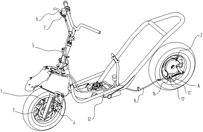
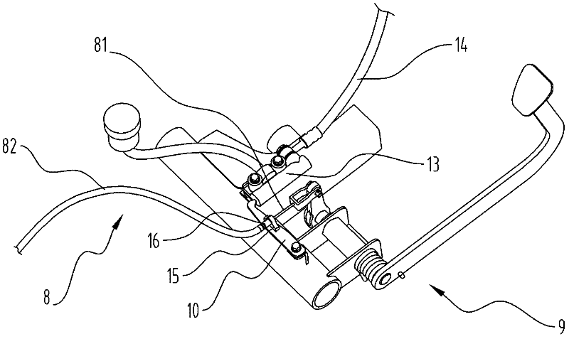
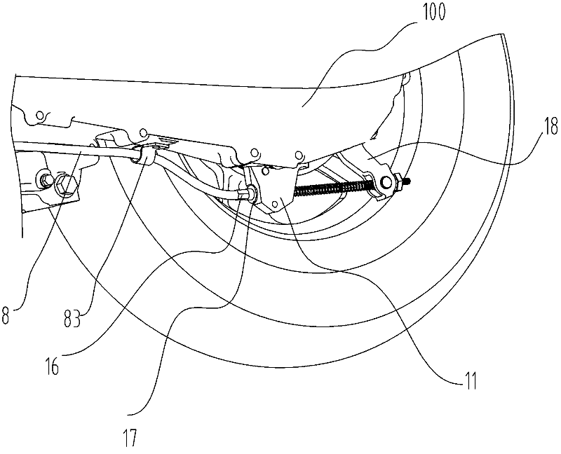
[0022] refer to Figure 1 to Figure 3 , the motorcycle braking system adopting the linkage mechanism of the present invention comprises a second brake 1 and a first brake 2, the second brake 1 is provided with a front brake disc 3 and a front brake caliper 4, and the front brake caliper 4 The first brake hose 5 is connected to the first master cylinder 7 operated by the front brake handle 6, and the first brake 2 is moved by the pull cable 8. The pull cable 8 includes an inner steel wire 81 and an empty sleeve on the inner steel wire. The outer tube 82, the two ends of the inner steel wire 81 are respectively connected with the first brake operating member 9 and the first brake 19, and the front and rear ends of the outer tube 82 are provided with a swing bar 10 and a limit block 11, The inner steel wire 81 passes through the swing bar 10 and the limit block 11, the outer tube 82 and the inner steel wire 81 are arranged in a curved manner between the limit block 11 and the swi...


PUM


Abstract

The invention discloses a force application mechanism for linkage and braking of a motorcycle, which comprises a cable. The cable comprises an inner steel wire and an outer tube sleeved on the inner steel wire, two ends of the inner steel wire are connected with a first braking operation part and a first brake respectively, an oscillating bar and a limiting block are arranged on the outer sides of the front end and the rear end of the outer tube respectively, the inner steel wire penetrates through the oscillating bar and the limiting block, the outer tube and the inner steel wire are crookedly arranged between the limiting block and the oscillating bar, the limiting block is fixed with a motorcycle body, the oscillating bar is pivoted to the motorcycle body and capable of oscillating round a pivoting point, the inner steel wire drives the outer tube to extend by operating the first braking operation part so as to push the oscillating bar to oscillate, and the oscillated oscillating bar starts a second brake to brake. When the first braking operation part is operated, the first brake acts by pulling the inner steel wire, and simultaneously, the inner steel wire drives the outer tube to extend, so that the oscillating bar can be pushed to lead the second brake to brake a front wheel of the motorcycle, combined braking of the front wheel and a rear wheel of the motorcycle is realized by the aid of a simple structure, operation of a driver is facilitated, and braking safety of the motorcycle is enhanced.

Description

technical field [0001] The invention relates to a linkage mechanism of a motor vehicle braking system. Background technique [0002] At present, the brakes of the front and rear wheels of motorcycles are generally controlled separately. The brakes of the front wheels are generally controlled by the handle installed on the steering handle, and the brakes of the rear wheels are generally controlled by Foot pedals on the frame operate the controls. In this way of separate control and control, normal gradual deceleration is adopted during the running of the motorcycle, and the motorcycle can be decelerated stably until it stops by controlling the rear wheel brake through independent manipulation of the pedals. When braking in an emergency, it is necessary to brake the front and rear wheels at the same time through the joystick and the pedals. 1. The synchronous braking of the rear wheels is more difficult to complete, especially at the moment of emergency braking, once the fro...

Claims


Application Information

Patent Timeline
Patent Type & Authority Applications(China)
IPC IPC(8): B62L3/08
Inventor 稻叶一美罗开军陈宏张义东
Owner JIANGMEN DACHANGJIANG GROUP CO LTD
Learn More