Brake hydraulic braking system and method
A technology of hydraulic brakes and brakes, which is applied in the direction of electric brake systems, brakes, brake transmissions, etc., can solve problems such as brake wear, vehicle safety hazards, and short service life of brakes, so as to improve stability and safety , the effect of reducing work intensity
- Summary
- Abstract
- Description
- Claims
- Application Information
AI Technical Summary
Problems solved by technology
Method used
Image
Examples
Embodiment 1
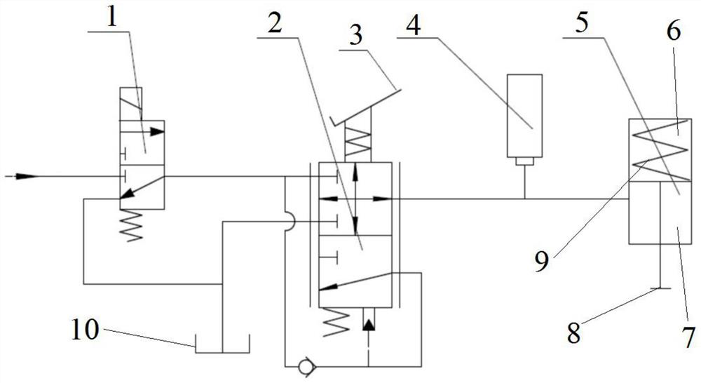
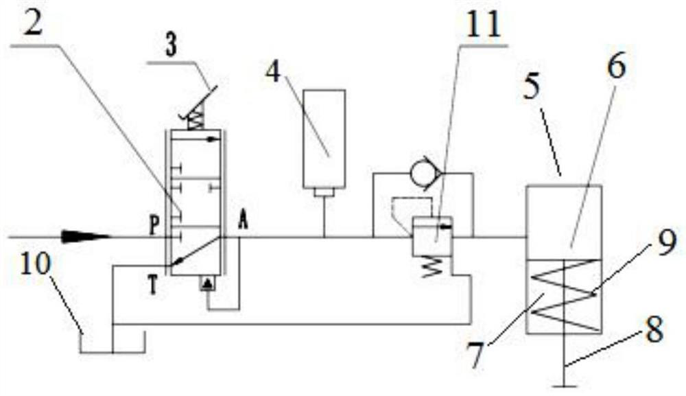
[0026] This embodiment provides a brake hydraulic braking system, including a brake pedal 3, a pressure regulating valve 2, and a pressure sensor 4, the brake pedal 3 is connected to the pressure regulating valve 2, and the movement of the brake pedal 3 is used to adjust the pressure regulating valve The oil pressure at the outlet of pressure regulating valve 2, the inlet of pressure regulating valve 2 is used to feed high-pressure oil, the pressure sensor 4 is used to measure the oil pressure at the outlet of pressure regulating valve 2, and the pressure sensor 4 is used to communicate with the electric feedback brake device connected, the electric regenerative braking device can adjust the braking force of the electric regenerative braking device according to the oil pressure detected by the pressure sensor 4, the outlet of the pressure regulating valve 2 is used to communicate with the piston cylinder 5 of the brake, and the outlet of the pressure regulating valve 2 The oil ...
Embodiment 2
[0028] This embodiment provides a brake hydraulic braking system, such as figure 1 As shown, the brake of the brake hydraulic brake system provided in this embodiment is a safety brake. The safety brake is a working mode in which the spring drives the brake fluid to drive the pressure to release.
[0029]In this embodiment, the pressure regulating valve 2 is that the greater the downward distance of the brake pedal 3, the smaller the oil pressure at the outlet of the pressure regulating valve 2. The piston cylinder 5 is provided with a piston rod 8, and the piston cylinder 5 includes a rod cavity 7 and The rodless chamber 6 is provided with a spring 9 for pushing the piston rod 8 out of the piston cylinder 5 in the rodless chamber 6, and the rod chamber 7 of the piston cylinder 5 communicates with the outlet of the pressure regulating valve 2; when the pressure sensor 4 detects When the oil pressure is lower than the maximum oil pressure at the outlet of the pressure regulati...
Embodiment 3
[0033] This embodiment provides a brake hydraulic braking system, such as figure 2 As shown, the difference from the second embodiment is that the brakes of the brake hydraulic braking system provided in this embodiment are non-safety brakes. The non-safety brake is a hydraulically actuated brake spring actuated and released working mode.
[0034] In this embodiment, the pressure regulating valve 2 is that the greater the downward distance of the brake pedal 3, the greater the oil pressure at the outlet of the pressure regulating valve 2. The piston cylinder 5 is provided with a piston rod 8, and the piston cylinder 5 includes a rod cavity 7 and The rodless chamber 6 and the rod chamber 7 are provided with a spring 9 for pushing the piston rod 8 to shrink into the piston cylinder 5. The rodless chamber 6 is connected with the outlet of the pressure regulating valve 2. When the oil pressure detected by the pressure sensor 4 When the hydraulic pressure is greater than that, th...
PUM
 Abstract
Description
Claims
Application Information
 - R&D
- Intellectual Property
- Life Sciences
- Materials
- Tech Scout
- Unparalleled Data Quality
- Higher Quality Content
- 60% Fewer Hallucinations
Browse by: Latest US Patents, China's latest patents, Technical Efficacy Thesaurus, Application Domain, Technology Topic, Popular Technical Reports.
© 2025 PatSnap. All rights reserved.Legal|Privacy policy|Modern Slavery Act Transparency Statement|Sitemap|About US| Contact US: help@patsnap.com


