Clamp device with improved structure for processing glass mould

A glass mold and structure improvement technology, applied in the field of tooling and fixtures, can solve problems such as scrapping, affecting the quality of joint surface and cavity milling, and achieve the effects of reducing work intensity, ensuring processing quality, and improving processing efficiency.

Active Publication Date: 2012-11-21
CHANGSHU JIANHUA MOLD TECH
View PDF4 Cites 50 Cited by
  • Summary
  • Abstract
  • Description
  • Claims
  • Application Information

AI Technical Summary

Problems solved by technology

As known in the industry, when clamping, the mold cavity of the glass mold half is upward, and the clamp clamps the outer part of the joint surface of the glass mold half, and the glass mold half is at a sufficient level. Guarantee the milling quality of the joint surface and the mold cavity; the second is to ensure the reliability of the clamping of the glass mold, and ensure that the pair of clamps used to clamp the half-mold of the glass mold have the function of locking (locking the half-mold of the glass mold) effect, because, in the process of processing the glass mold half, if the degree of clamping of the glass mold half by the clamp table is even slightly loose, then it will seriously affect the joint surface and film of the glass mold half. The quality of the milling process of the cavity, even causing scrap

Method used


Image

  • Clamp device with improved structure for processing glass mould
  • Clamp device with improved structure for processing glass mould
  • Clamp device with improved structure for processing glass mould

Examples


Embodiment Construction

[0018] In order to enable the examiners of the patent office, especially the public, to understand the technical essence and beneficial effects of the present invention more clearly, the applicant will describe in detail the following in the form of examples, but none of the descriptions to the examples is an explanation of the solutions of the present invention. Any equivalent transformation made according to the concept of the present invention which is merely formal but not substantive shall be regarded as the scope of the technical solution of the present invention.

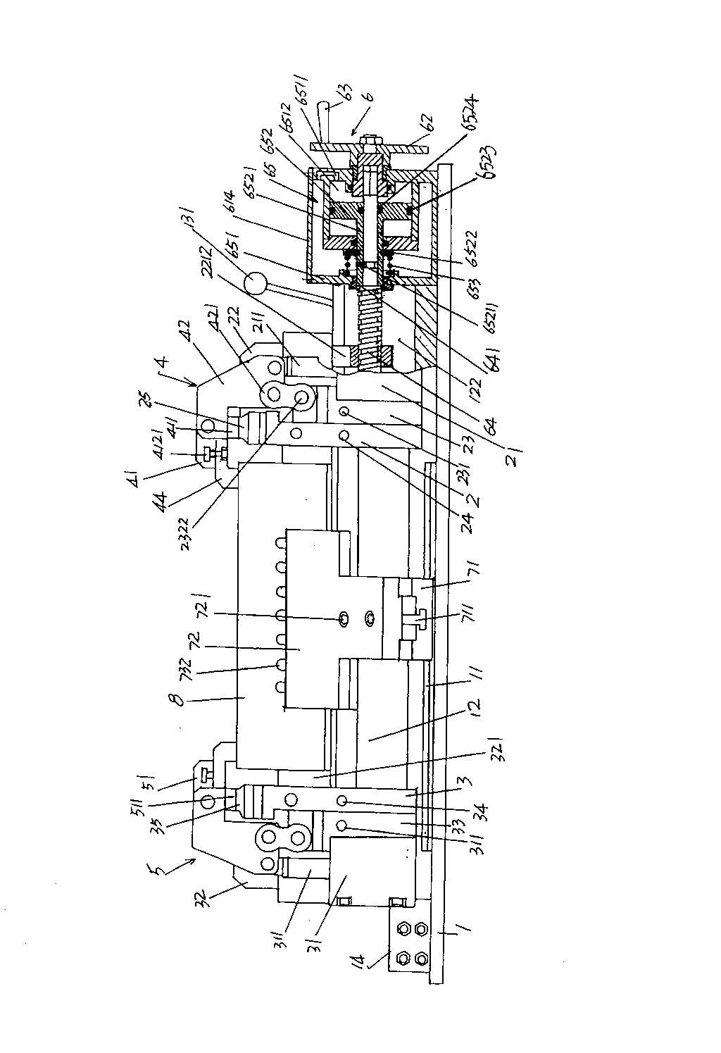
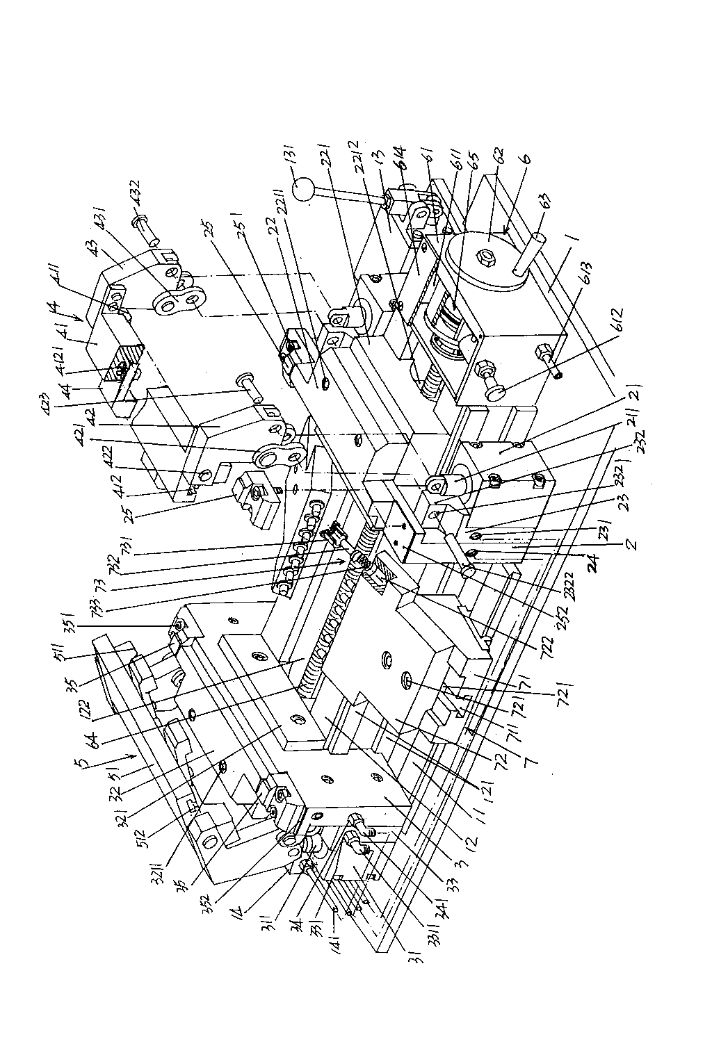
[0019] Please see figure 1 and figure 2 , in the figure 1 and figure 2 Provides a base 1 that is generally rectangular parallelepiped, and the base 1 is fixed on a numerically controlled machine tool or similar equipment during use. Depend on figure 1 As shown, a guide rail bar 11 is formed on the longitudinal direction of the base 1, that is, both sides of the length direction and the surfac...


PUM


Abstract

The invention discloses a clamp device with an improved structure for processing a glass mould, and belongs to the technical field of tooling clamps. The clamp device comprises a base, a first clamp platform fixed mount, a second clamp platform fixed mount, a first mould horizontal adjusting mechanism, a second horizontal adjusting mechanism, a clamp platform driving mechanism and a pair of horizontal adjusting mechanisms, wherein guide rail bars are arranged on two sides of the base respectively, a clamp platform fixed mount sliding seat is arranged between the guide rail bars, and a pair ofguide rails and a clamp platform moving chamber are formed on the clamp platform fixed mount sliding seat respectively; the first clamp platform fixed mount and the second clamp platform fixed mount are positioned on the base, a first acting cylinder and a second acting cylinder are fixed at two ends of the first clamp platform fixed mount and the second clamp platform fixed mount respectively, afirst clamp platform fixed seat and a second clamp platform fixed seat are fixed in the middle parts of the first clamp platform fixed mount and the second clamp platform fixed mount respectively, and a first clamp platform and a second clamp platform are fixed on the first clamp platform fixed seat and the second clamp platform fixed seat respectively; the first mould horizontal adjusting mechanism and the second mould horizontal adjusting mechanism are arranged on the first clamp platform fixed mount and the second clamp platform fixed mount; the clamp platform driving mechanism is arrangedon the base; the two horizontal adjusting mechanisms are arranged on a pair of guide rail bars; and the clamp platform driving mechanism comprises a box body, a handle plate, a handle, a screw rod and a clamp platform locking device. The clamp device has the advantages that: once clamping is embodied, the operating strength is reduced, and the working efficiency is improved.

Description

technical field [0001] The invention belongs to the technical field of fixtures, and in particular relates to a fixture device with improved structure for processing glass molds. Background technique [0002] Fixtures play a very important role in the production of industrial products, and the production of glass molds is no exception. The so-called tooling mold refers to special equipment or tools used to clamp or position workpieces in machining to meet certain process requirements. Fixtures usually need to meet the requirements of no interference during product production, accurate and reliable positioning, and convenient operation. Since the tooling fixture has the exclusive characteristics of manufacturing a certain product, the degree of generalization is low, and it is often made by the manufacturer of mechanical products. Glass mold manufacturers also mostly equip various tooling fixtures in a self-made way. In recent years, although all kinds of medium and high-en...

Claims


Application Information

Patent Timeline
Patent Type & Authority Patents(China)
IPC IPC(8): B23Q3/08B23Q7/00
Inventor 马建华晏庆宝朱伟国沈军韩志强
Owner CHANGSHU JIANHUA MOLD TECH
Why Eureka
Try Eureka