Security device for smart home

A smart home and door leaf technology, applied in the field of home security, can solve the problems of the electromagnetic lock losing the locking effect, the door leaf cannot be easily opened, and the power consumption is high.

Active Publication Date: 2021-09-03
NANJING FORESTRY UNIV
View PDF7 Cites 1 Cited by
  • Summary
  • Abstract
  • Description
  • Claims
  • Application Information

AI Technical Summary

Problems solved by technology

That is, when the door leaf is closed, it is necessary to keep the circuit connected to the silicon steel sheet continuously energized, which consumes a lot of power; and once the power supply system of the house is powered off, the electromagnet...

Method used


Image

  • Security device for smart home
  • Security device for smart home
  • Security device for smart home

Examples


Embodiment 1

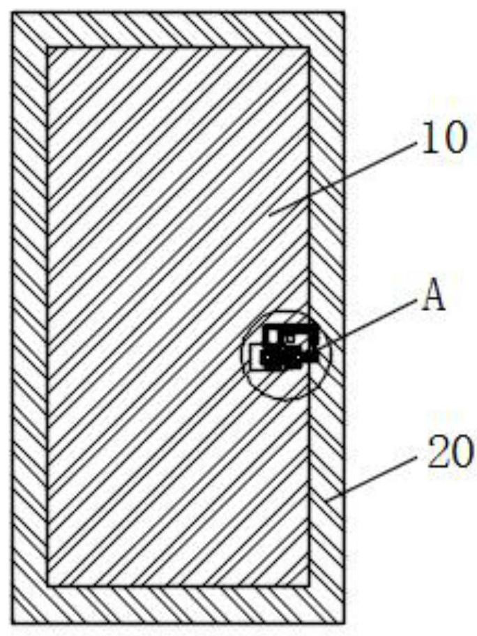
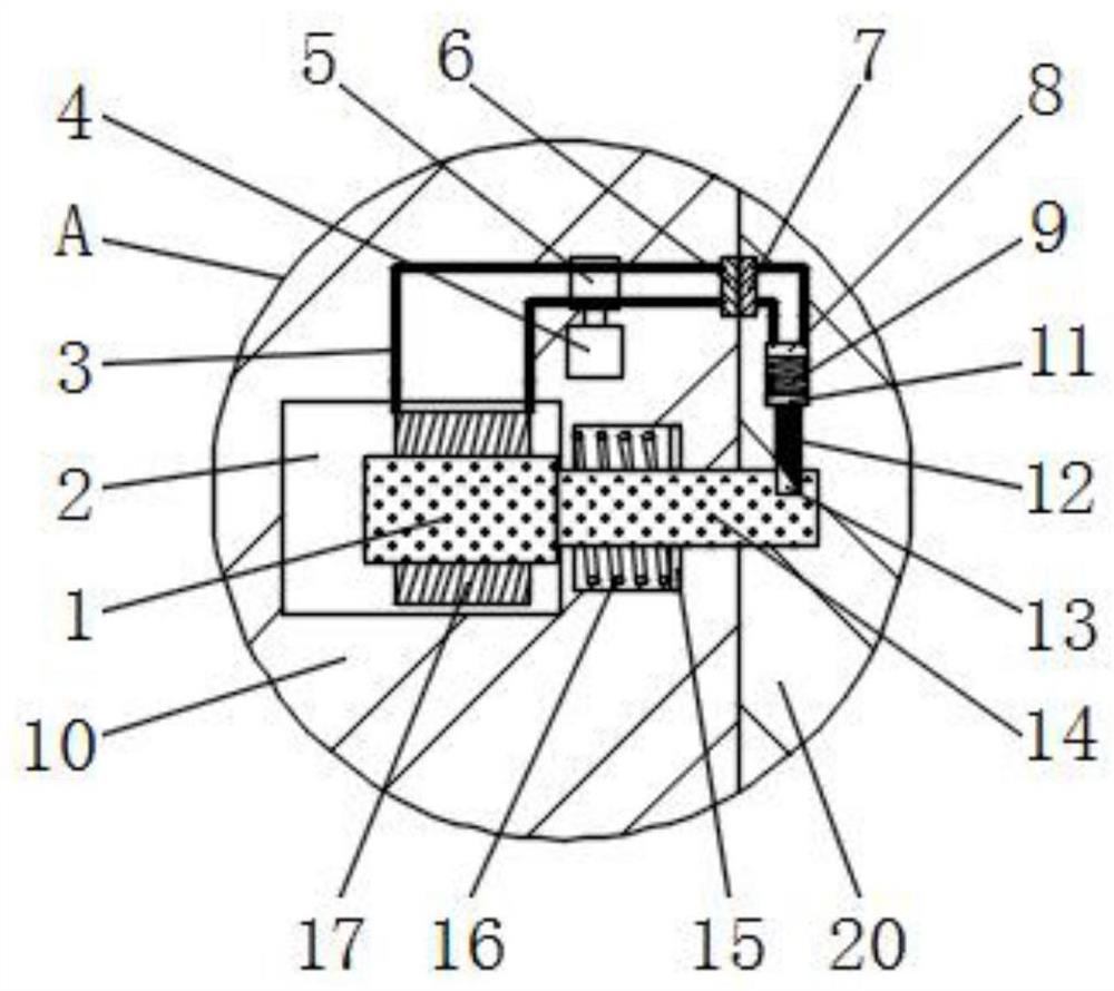
[0035] Such as figure 1 The shown security device for smart home includes a door leaf 10 and a door frame 20, one side of the door leaf 10 is hinged to the corresponding side of the door frame 20, and the side of the door leaf 10 facing away from the hinged side is connected to the door frame 20. There is an electromagnetic lock between; figure 2 As shown, the electromagnetic lock includes a lock tongue 14 installed laterally in the door 10, a lock hole provided on the door frame 20 for the lock tongue 14 to insert, and a power supply unit for power supply. The lock tongue 14 faces away from the One end of the lock hole is fixed with an armature 1, the outer side of the armature 1 is set with a coil 17, and the door leaf 10 is provided with a first installation cavity 2 for installing the lock tongue 14 and related components, and the lock tongue 14 is fixed with a An ear plate 15, the side of the ear plate 15 facing away from the lock hole is connected with a second spring ...

Embodiment 2

[0043] The difference between this embodiment and embodiment 1 is:

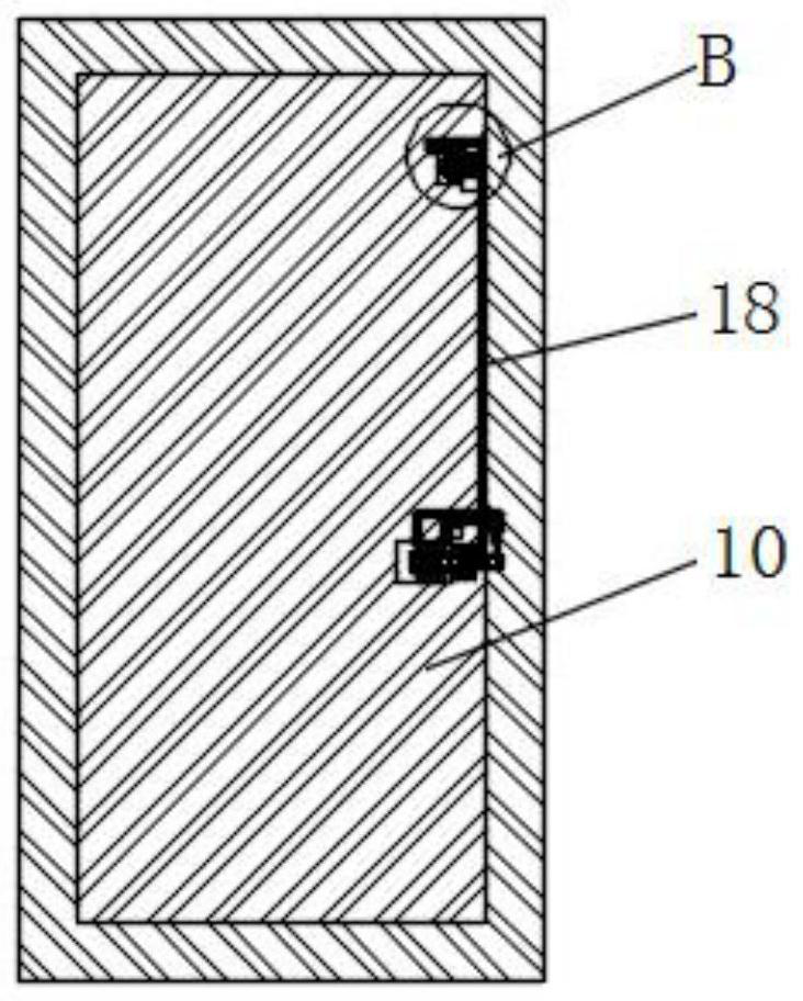
[0044] In this example, if image 3 and Figure 4 As shown, the side of the door leaf 10 facing away from the hinged side is provided with a second insertion rod 18 arranged longitudinally that can be inserted into the locking groove 13, and the inside of the door leaf 10 is provided with a bar-shaped groove for the second insertion rod 18 to move; The upper end of the side of the door leaf 10 facing away from the hinged side is provided with a second installation cavity 27, and the carrier plate 23 is provided in the second installation cavity 27 and is connected to the carrier plate 23 through the first bearing 25 through the first bearing 25. and the third spring 24 connected to the side of the carrier plate 23 towards the hinged side of the door leaf 10, the rotating rod 26 and the third spring 24 are all horizontally arranged, and the elastic action of the third spring 24 produces a force on the carrier...


PUM


Abstract

The invention discloses a security device for smart home, and belongs to the field of home security. The security device comprises a door leaf, a door frame and an electromagnetic lock. The electromagnetic lock comprises a lock tongue, a lock hole and a power supply unit, wherein an armature is fixed at one end, back to the lock hole, of the lock tongue, the outer side of the armature is sleeved with a coil, and the lock tongue is sleeved with a second spring; a locking groove is formed in one end of the spring bolt, a first inserting rod used for being inserted into the locking groove is installed in the door frame, and an iron block, a first spring and an electromagnet are sequentially arranged on the side, back to the lock hole, of the first inserting rod. The power supply unit comprises a power source and a wire electrically connected with the coil and the electromagnet, wherein an electric switch is arranged between the power source and the wire, a door lock control panel is installed on the front face of the door leaf, an access control recognition device and a power-on button are arranged on the door lock control panel, and the electric switch is electrically connected with the output end of the access control recognition device. The electric quantity consumption can be greatly reduced, the locking effect can be kept when a house power supply system is powered off, and the anti-theft function is good; and the trouble caused by accidental closing of the door leaf can be effectively avoided.

Description

technical field [0001] The invention relates to the field of home security, in particular to a security device for smart homes. Background technique [0002] Smart home is based on the residence as a platform, using integrated wiring technology, network communication technology, security technology, automatic control technology, audio and video technology to integrate the facilities related to home life, to build an efficient management system for residential facilities and family schedules, and to improve Home safety, convenience, comfort, artistry, and to achieve an environmentally friendly and energy-saving living environment. [0003] Doors and windows are a main channel for thieves to enter the house for real-time theft. The traditional door leaf is only locked by a simple door lock, and its anti-theft effect is relatively poor. The design of the electromagnetic lock (or magnetic lock) is the same as that of the electromagnet, which uses the principle of electromagneti...

Claims


Application Information

Patent Timeline
IPC IPC(8): E05B47/00E05B15/00E05B15/10E05B17/20E05B63/00E05B65/00
CPCE05B47/0002E05B15/00E05B15/10E05B17/2007E05B17/2084E05B65/00E05B63/00
Inventor 任新宇关惠元徐伟张耀引刘传兵吴振韩高锐涛
Owner NANJING FORESTRY UNIV
Why Eureka
Try Eureka