Supercharge Your Innovation With Domain-Expert AI Agents!

Frame interpolation apparatus and method

An interpolation and frame interpolation technology, applied in the field of frame interpolation devices, can solve the problems of inability to properly correct images, blurred object contours, and high reliability, and achieve the effect of smooth flickering motion and less flickering.

Inactive Publication Date: 2012-07-11
MITSUBISHI ELECTRIC CORP
View PDF5 Cites 6 Cited by
  • Summary
  • Abstract
  • Description
  • Claims
  • Application Information

AI Technical Summary

Problems solved by technology

The flaw in doing the correction prevents the image from mostly using the average image of the previous and previous frames, resulting in the problem that the outline of the object looks blurry
Also, due to repeated patterns, etc., although a motion vector different from the true motion vector is detected, the result is also similar due to pixel values, so that the reliability becomes higher than it should be, and in this case, there is a possibility that the image cannot be corrected properly. disordered problem

Method used


Image

  • Frame interpolation apparatus and method
  • Frame interpolation apparatus and method
  • Frame interpolation apparatus and method

Examples


Embodiment approach 1

[0028] Hereinafter, Embodiment 1 of the present invention will be described with reference to the drawings.

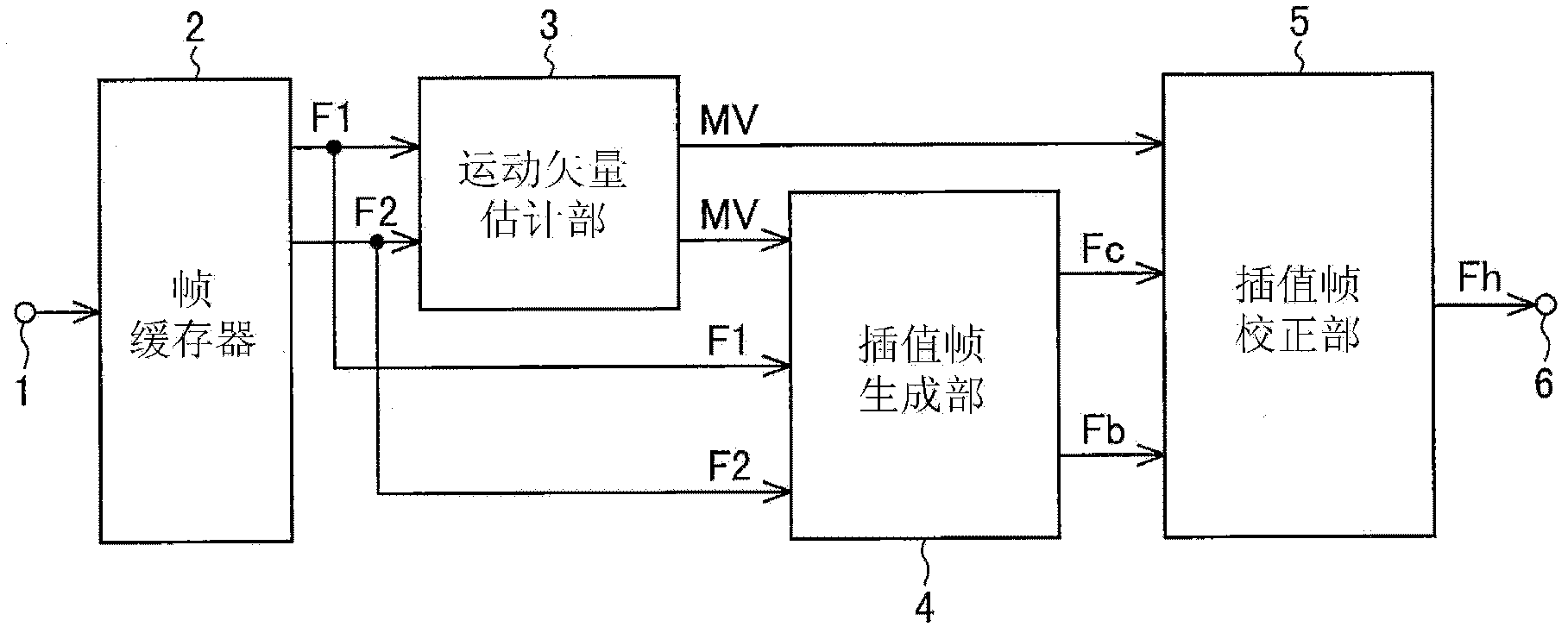
[0029] figure 1 It is a block diagram showing the frame interpolation device according to Embodiment 1 of the present invention. The illustrated frame interpolation device has a video input terminal 1 , a frame buffer 2 , a motion vector estimation unit 3 , an interpolation frame generation unit 4 , an interpolation frame correction unit 5 , and an interpolation frame output terminal 6 .

[0030] Video input from video input terminal 1 is stored in frame buffer 2 .

[0031] The motion vector estimation unit 3 receives the data of the first frame F1 and the second frame F2 read from the frame buffer 2 (hereinafter, "frame data" may be simply referred to as "frame") and outputs a motion vector MV. Here, the first frame F1 is the latest frame (current frame), and the second frame F2 is a frame (past frame) temporally earlier than the first frame F1.

[0032] The interp...

Embodiment approach 2

[0152] Embodiment 2 of the present invention will be described below.

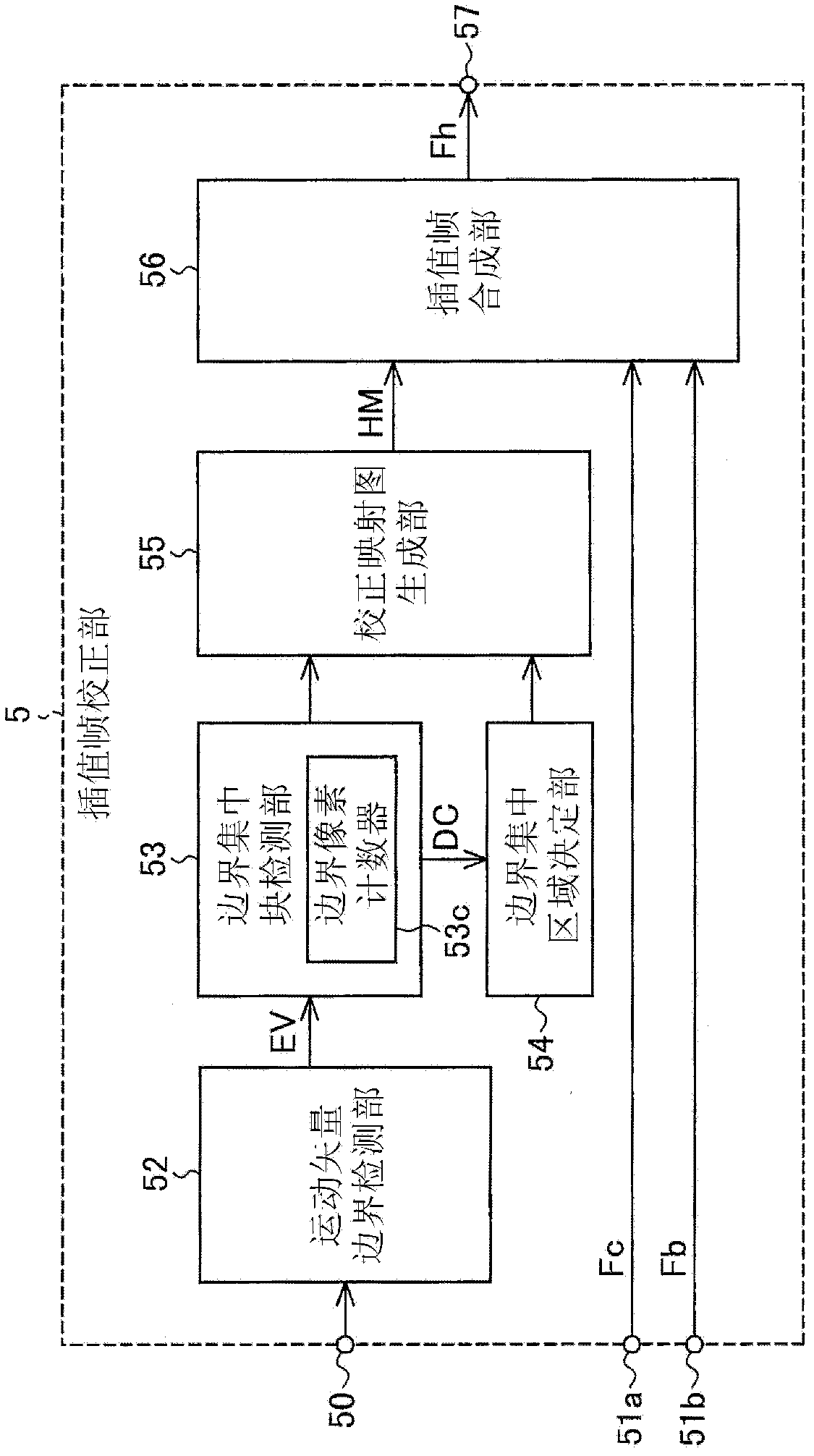
[0153] The overall structure of the frame interpolation device of Embodiment 2 is as follows figure 1 shown, but the structure of the interpolation frame corrector 5 and the reference image 3 The structure of Embodiment 1 described above is different, and the structure of the interpolation frame correction unit 5 of this embodiment is, for example, as follows Figure 15 constructed as shown. Figure 15 The illustrated interpolation frame correction section 5 differs in that instead of image 3 Instead of the boundary concentration area determination unit 54, the boundary concentration area determination unit 58 is used. Motion vector boundary detection unit 52, boundary concentrated block detection unit 53, correction map generation unit 55, interpolation frame synthesis unit 56 and image 3 Same as shown.

[0154] Figure 4 Boundary concentration area determination unit 54 has obtained the geometri...


PUM


Abstract

The invention provides a frame interpolation apparatus and a method thereof. The invention restrains the blurring and the shaking of dynamic images in video to form high definition interpolated frames (Fh) achieving smooth motions. To be a solution, a motion-compensated interpolated frame (Fc) is corrected according to the boundary of a motion vector (MV). The motion-compensated interpolated frame (Fc) is generated according to the motion vector (MV) obtained by a motion vector estimate section (4). Positions at which an absolute value of a first or second derivative of the motion vectors is not less than a predetermined amount are found to be at a motion vector (MV) boundary, and the pixel values of the pixels of the motion-compensated interpolated frame (Fc) in an area where boundary pixels are concentrated are corrected. Blocks with at least a predetermined proportion of boundary pixels are found to be in an area where boundary pixels are concentrated.

Description

technical field [0001] The present invention relates to a frame interpolation device and method for smoothing moving images by using a plurality of frames of images included in a video signal and generating interpolation frame images between these frames. The present invention also relates to a program used in implementing the frame interpolation method, and a recording medium on which the program is recorded. Background technique [0002] A sustain-type image display device such as an LCD TV continues to display the same image during one frame period. For a moving object in the image, the human eye follows the moving object. On the other hand, the displayed position is the same within one frame period, so There is a problem that the border part looks blurry. In view of this, consider the following situation: increase the number of display frames by interpolating frames, make the position of the displayed object follow the motion, and change the position slightly, thereby s...

Claims


Application Information

Patent Timeline
Patent Type & Authority Applications(China)
IPC IPC(8): H04N7/01
CPCH04N5/145H04N7/014
Inventor 那须督小野良树久保俊明藤山直之堀部知笃
Owner MITSUBISHI ELECTRIC CORP
Features
  • R&D
  • Intellectual Property
  • Life Sciences
  • Materials
  • Tech Scout
  • Unparalleled Data Quality
  • Higher Quality Content
  • 60% Fewer Hallucinations
Learn More