Compression garments and method of manufacture

A clothing and piece technology, applied in the field of pressurized clothing

Active Publication Date: 2012-07-11
ITOCHU CO LTD
View PDF7 Cites 10 Cited by
  • Summary
  • Abstract
  • Description
  • Claims
  • Application Information

AI Technical Summary

Problems solved by technology

[0007] Excessive pressure provided by compression garments has been found to cause friction of the ITB on the hip and knee joints, leading to or increasing ITBFS

Method used


Image

  • Compression garments and method of manufacture
  • Compression garments and method of manufacture
  • Compression garments and method of manufacture

Examples


Embodiment Construction

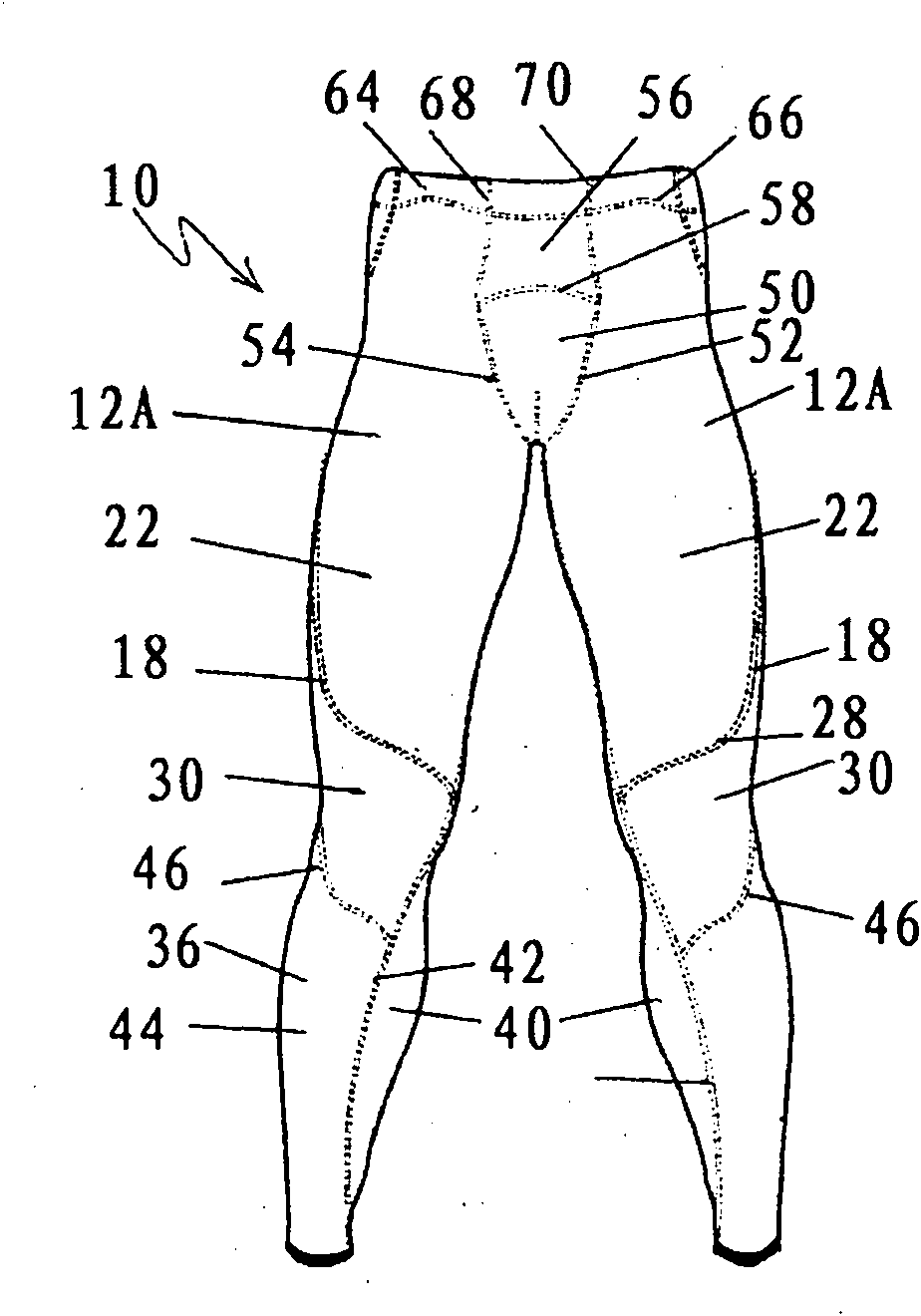
[0048] first reference Figures 1 to 3 , the compression garment 10 is shown as a lower body garment in the form of a long tight garment intended to cover the body portion of the lower torso from approximately the wearer's waistline to the wearer's ankles.

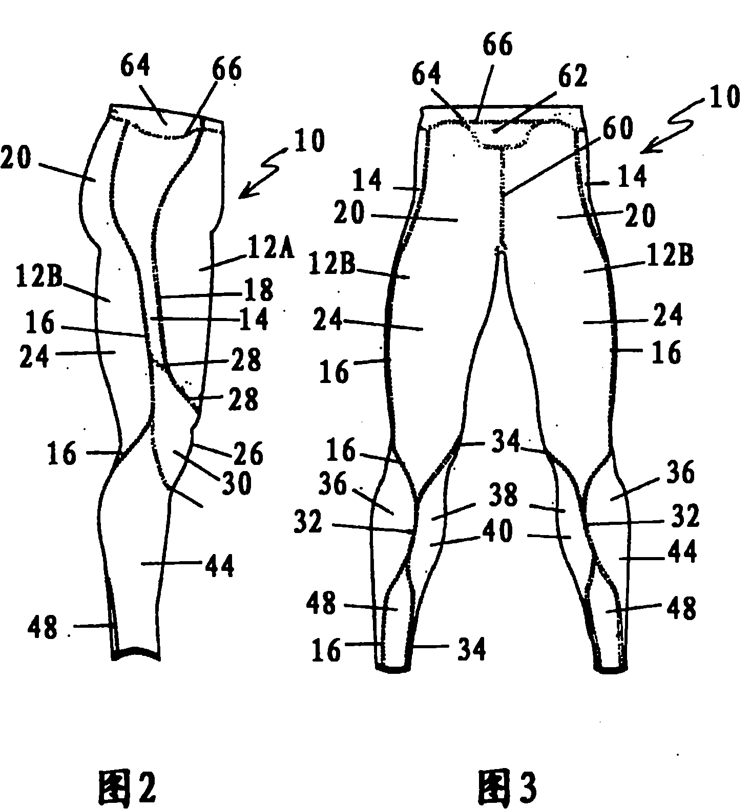
[0049] Long tights 10 have first panels 12A and 12B of extensible material and a second panel 14 of extensible material. The first panel 12A is connected to the second panel 14 by a second seam 18 . The first panel 12B is connected to the second panel 14 by a first seam 16 . Effectively, first piece 12 is divided into two parts, 12A and 12B, and piece 12A is as figure 1 Covering the front of the wearer's thighs as shown in , and piece 12B as in image 3 The seam (not shown) connecting panels 12A and 12B extends along the wearer's inner thigh.

[0050] The first panels 12A and 12B require more force to stretch and are therefore less elastic than the second panel 14 .

[0051] The first panel 12B is adapted to support t...


PUM


Abstract

This invention relates to a compression garment (10) for clothing a body part including a lower body part of a wearer. The compression garment has a first panel (12) of stretchable material joined to a second panel (14) of stretchable material by a first seam (16). The stretchable material of the second panel (14) has a higher stretch and recovery characteristic compared to the stretchable material of the first panel (12). In use, the first panel (12) of stretchable material is adapted to support a larger, more powerful muscle group than the second panel (14). The second panel (14) is joined to a third panel or the first panel (12) by a second seam (18). The second panel (14) is adapted in use to be located along a substantial part of the illiotibial band of the wearer.

Description

technical field [0001] The present invention relates to compression garments and to methods of manufacture. In particular, the present invention relates to compression garments comprising an upper body garment and a lower body garment. Background technique [0002] Prior art compression garments are generally designed to fit snugly to the body, but do not take into account the extent to which muscles increase in size and mass during activity. In this case, such prior art garments can become non-static or reverse gradient. Once a person wearing a static compression garment gains muscle mass through activity, the garment can become tighter around that muscle, which can increase in volume by as much as 3-5%. This alters the effect of static compression and can have the undesired effect of becoming undesirably tight or providing greater compression in the wrong location. This can impede circulation and reduce the effectiveness of lymphatic drainage. [0003] Prior art compre...

Claims


Application Information

Patent Timeline
Patent Type & Authority Applications(China)
IPC IPC(8): A41D13/05A41D27/00
CPCA61F13/08A41D13/0015A41D2300/22A41D2400/60A41D31/12A41D31/185A41B9/04A41C1/18A41D13/05A41D27/00
Inventor J·麦克拉伦A·赫洛德P·巴顿
Owner ITOCHU CO LTD
Why Eureka
Try Eureka