Video encoding device, video decoding device, and data structure

A technology for moving images and encoding devices, which is applied in image communication, digital video signal modification, television and other directions, and can solve the problems of decreased prediction accuracy, unused, and decreased coding efficiency.

Inactive Publication Date: 2012-07-11
SHARP KK
View PDF3 Cites 0 Cited by
  • Summary
  • Abstract
  • Description
  • Claims
  • Application Information

AI Technical Summary

Problems solved by technology

In MV Competition, since a flag indicating which vector predictor candidate is selected from among a plurality of vector predictor candidates is encoded as a vector predictor for encoding, when a motion vector candidate with low precision is used, there may be a problem with The coding efficiency will de

Method used


Image

  • Video encoding device, video decoding device, and data structure
  • Video encoding device, video decoding device, and data structure
  • Video encoding device, video decoding device, and data structure

Examples


Deformed example 1

[0188] The present invention is not limited to the above-mentioned embodiments. Below, refer to Figure 10 A video encoding device according to a first modification example of the present invention will be described.

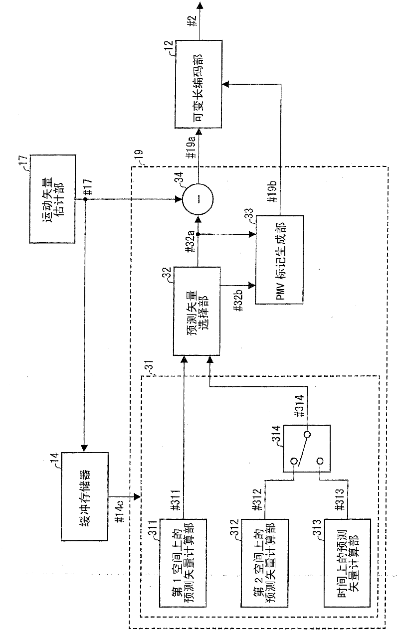
[0189] Figure 10 It is a block diagram showing the configuration of the motion vector redundancy reduction unit 19 included in the video decoding device according to this modification. Other configurations of the video encoding device according to this modification are the same as those of the video encoding device 1 in the first embodiment.

[0190] like Figure 10 As shown, in this modified example, the candidate vector predictor generating unit 31 includes a candidate vector predictor selecting unit 315 instead of the candidate vector predictor selecting unit 314 .

[0191] The vector predictor candidate selection unit 315 selects any one of the second spatial vector predictor candidate #312 and the temporal vector predictor candidate #313 according to t...

Deformed example 2

[0210] Hereinafter, a video encoding device according to a second modification example of the present invention will be described. The video encoding device according to the second modified example of the present invention includes a vector predictor candidate selection unit 316 instead of the vector predictor candidate selection unit 314 in the video encoding device 1 . Other configurations of the video encoding device according to this modification are the same as those of the video encoding device 1 in the first embodiment.

[0211] The vector predictor candidate selection unit 316 selects any one of the second spatial vector predictor candidate #312 and the temporal vector predictor candidate #313 based on the frame interval between the frame including the target partition and the frame including the co-located partition. One vector predictor candidate is set as the second vector predictor candidate #316.

[0212] More specifically, the vector predictor candidate selectio...

Deformed example 3

[0223] Hereinafter, a video encoding device according to a third modification example of the present invention will be described. The video coding device according to the third modification of the present invention includes a vector predictor candidate selection unit 317 instead of the vector predictor candidate selection unit 314 in the video coding device 1 . Other configurations of the video encoding device according to this modification are the same as those of the video encoding device 1 in the first embodiment.

[0224] The vector predictor candidate selection unit 317 selects either one or both of the frame including the target partition and the frame including the co-located partition into a GOP (Group of Picture) structure (group of pictures) consisting of pictures including B pictures. group structure), the second spatial predictor candidate #312 is selected, and when the frame including the target partition and the frame including the co-located partition do not bel...


PUM


Abstract

On the basis of coding cost, a prediction vector candidate to be used as a prediction vector is selected from a first prediction vector candidate which is the median of the motion vectors allocated to the partitions around a partition to be encoded; and another prediction candidate which is selected from a second prediction vector candidate, which is the motion vector allocated to the contiguous partition on the left side of the partition to be encoded, and a third prediction vector candidate, which is the motion vector allocated to the collocated partition which occupies the same position in the decoded frame as the partition to be encoded, on the basis of the prediction accuracy of the third prediction vector candidate.

Description

technical field [0001] The present invention relates to a video encoding device that encodes video to generate encoded data. Also, it relates to a video decoding device that decodes coded data generated using such a video coding device. Background technique [0002] In order to efficiently transmit or record moving pictures, moving picture encoding devices are used. Also, motion compensation prediction using motion vectors is used for encoding of moving images in the moving image coding apparatus. H264 / AVC etc. are mentioned as a video coding method using motion compensation prediction. [0003] As a conventional general technique, a method is known in which an input moving image is divided into a plurality of partitions for each frame, and a partition to be coded (hereinafter referred to as a partition) is used among the plurality of partitions. The median (median value) of the motion vectors assigned to the left adjacent partition of the "object partition", the partitio...

Claims


Application Information

Patent Timeline
IPC IPC(8): H04N7/32
CPCH04N19/00781H04N7/26829H04N19/0066H04N19/00648H04N7/2684H04N7/50H04N19/56H04N19/61H04N19/553
Inventor 北浦嘉浩猪饲知宏
Owner SHARP KK
Why Eureka
Try Eureka