L-shaped baffle block type lead end grounding clamp

A grounding clip and wire end technology, applied in the direction of conductive connection, connection, electrical component connection, etc., can solve the problems of easy sliding of the wire and inconvenient operation, and achieve the improvement of the anti-drop effect, the prevention of relative rotation, and the perfect anti-drop performance. Effect

Active Publication Date: 2012-07-18
ELECTRIC POWER RES INST OF GUANGXI POWER GRID CO LTD
View PDF6 Cites 9 Cited by
  • Summary
  • Abstract
  • Description
  • Claims
  • Application Information

AI Technical Summary

Problems solved by technology

The large-diameter wire is located at the lower part of the tongue, that is, the bottom of the eight-shaped clamp, and the wire is easy to slip
In addition, the spiral grounding clamp is also widely used in industry because it holds the wire firmly. The spiral grounding clamp includes a chuck, a horizontal locking lever and an operating lever. The chuck is arranged in a U shape horizontally, forming A jaw opening in the horizontal direction, the horizontal locking rod is installed in the jaw and connected with the operating rod to form a T-shaped connection body. The operating rod and the bottom edge of the chuck are connected by threads. The horizontal locking rod is connected as a whole, which can drive the horizontal clamping rod to rise and fall in the jaw, so as to clamp or release the wire. However, because the jaw has a certain opening, the wire is clamped by thread adjustment, and the operating rod needs to be twisted. It takes a lot of turns to make the horizontal locking lever lock the wire in the jaw, which is very inconvenient to operate

Method used


Image

  • L-shaped baffle block type lead end grounding clamp
  • L-shaped baffle block type lead end grounding clamp
  • L-shaped baffle block type lead end grounding clamp

Examples


Embodiment Construction

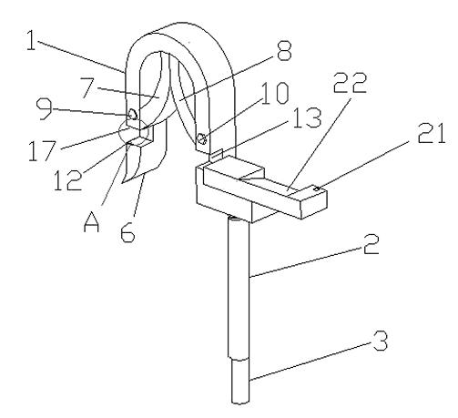
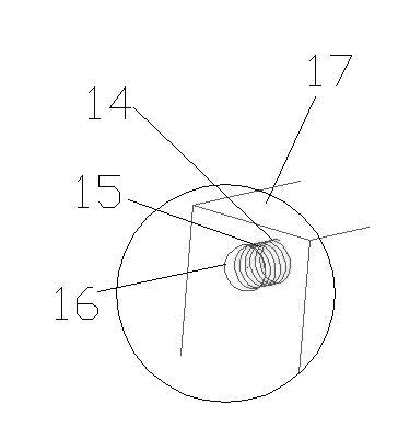
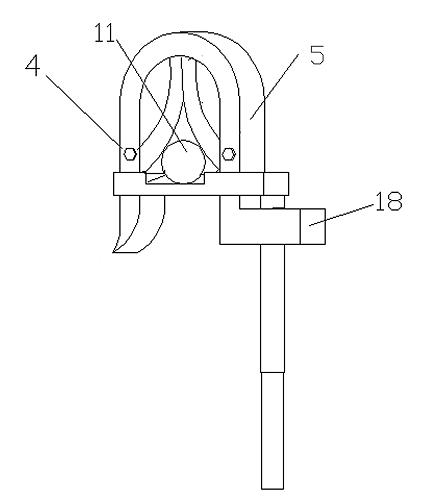
[0013] Such as figure 1 As shown, the grounding clamp of the present invention includes a hook 1 with a grounding wire end, an L-shaped high-voltage line anti-falling mechanism 2 and an operating rod 3 . The hook 1 includes a left clamping part 4 , a right clamping part 5 and a bending part 6 connecting the clamping parts. Described left clamping part 4 is parallel with right clamping part 5, and left clamping part 4, right clamping part 5 are connected with rotatable left tongue piece 7, right tongue piece 8 respectively, and are respectively positioned at left tongue piece 7 and the left tension spring 9 between the left clamping part 4, the right tension spring 10 of the right tongue 8 and the right clamping part 5. The left tongue piece 7 is arranged opposite to the right tongue piece 8 to form a splayed jaw for clamping the wire 11 . The bottom ends of the left clamping part 4 and the right clamping part 5 are respectively provided with a groove at the same horizontal p...


PUM


Abstract

The invention relates to an L-shaped baffle block type lead end grounding clamp, which comprises a hanger provided with a grounding lead end and an operating rod, wherein the hanger comprises a left clamping part and a right clamping part, the left clamping part and the right clamping are internally connected with two rotatable tongue pieces, a horizontal boss extends out of the edge of the right clamping part, the horizontal boss is rotatably connected with the operating rod, the end of the operating rod is connected with a horizontal lock rod, and the hanger is internally provided with a lock port matched with the horizontal lock rod. The L-shaped baffle block type lead end grounding clamp further comprises a locking device capable of locking the horizontal lock rod in the lock port of the hanger. After a lead is clamped by a splayed clamping port formed by the two tongue pieces, the operating rod is rotated to make the horizontal rod enter the lock port, and the horizontal lock rod is blocked under the lead so as to prevent the lead from dropping from the clamping port. The L-shaped baffle block type lead end grounding clamp is easy to operate. Meanwhile, a locking device is arranged between the hanger and the horizontal lock rod, so that the phenomenon that the horizontal rod rotates relative to the hanger in the strong wind environment is eliminated, and the anti-dropping effect is enhanced.

Description

technical field [0001] The invention relates to a grounding wire clip, in particular to an L-shaped block-type wire end grounding wire clip. Background technique [0002] The grounding clamp at the wire end is a safety device used to temporarily short-circuit and ground the power-off transmission wire. Its function is to prevent the harm to the human body caused by the sudden incoming power or the induced voltage generated by the adjacent high-voltage live equipment during the maintenance of the high-voltage transmission wire. At present, the grounding clamps used by various power grid companies mainly include spiral type, duck tongue type, flat type and impact type. The duck tongue type is widely used because the clamping force generated when clamping the wire is relatively balanced, and it is relatively easy to operate. Its main structure is composed of a hook, two tongues, an operating rod, and two tension springs. The operating rod is connected to the hook. The hook has...

Claims


Application Information

Patent Timeline
Patent Type & Authority Applications(China)
IPC IPC(8): H01R11/14H01R4/48
Inventor 许飞王凯李岩舟陈渊滕庆庆官丽金汪丽川周柯蒋学军徐波滕辉
Owner ELECTRIC POWER RES INST OF GUANGXI POWER GRID CO LTD
Why Eureka
Try Eureka