
Expansion bar

A telescopic rod and sliding rod technology, applied in the field of telescopic rods, can solve the problems of telescopic length limitation, large side force, easy to fall off, etc., and achieve the effects of tight connection, avoidance of impact, and prevention of rotation

Inactive Publication Date: 2010-11-17
OCEANS KING LIGHTING SCI&TECH CO LTD +1
View PDF0 Cites 20 Cited by
  • Summary
  • Abstract
  • Description
  • Claims
  • Application Information

AI Technical Summary

Problems solved by technology

Although the latch structure can solve the problems of anti-rotation and positioning, the latch is easy to fall off and break, especially in vibration situations.
In addition, the height of the extension will be limited by the positioning height
[0005] Mechanical telescopic rods are generally two-section type, which limits the telescopic length, and has the defect of not being able to withstand large side forces, making it even less firm in vibration situations
During the lifting process of the telescopic pole, before it is fixed, one of the poles is easy to fall, causing impact on the bottom, which may damage related components
When the telescopic pole is assembled with other components, the installation and fixing procedures are complicated and maintenance is inconvenient

Method used


Image

  • Expansion bar
  • Expansion bar
  • Expansion bar

Examples


Embodiment Construction

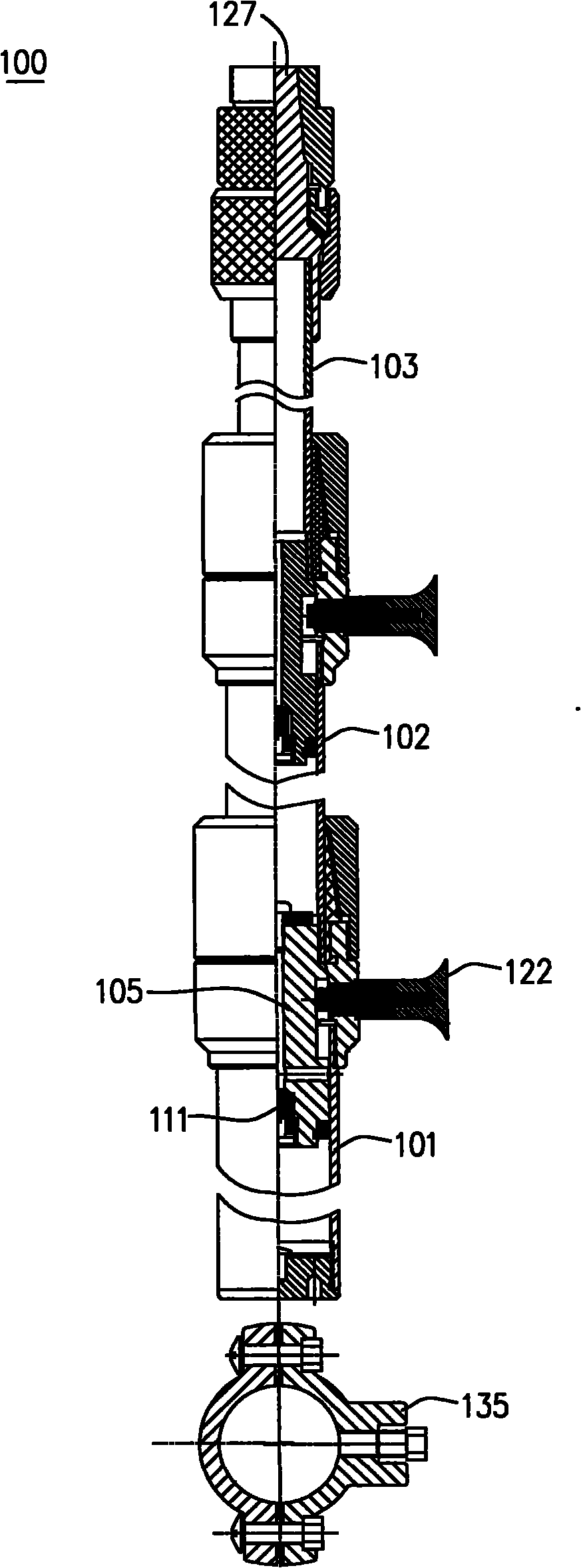
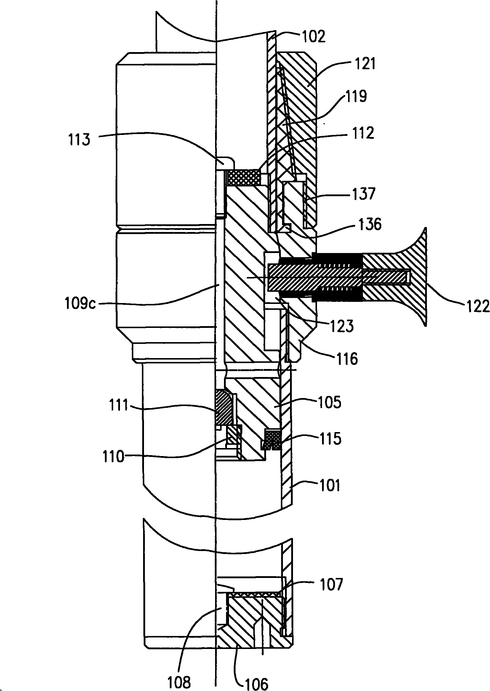
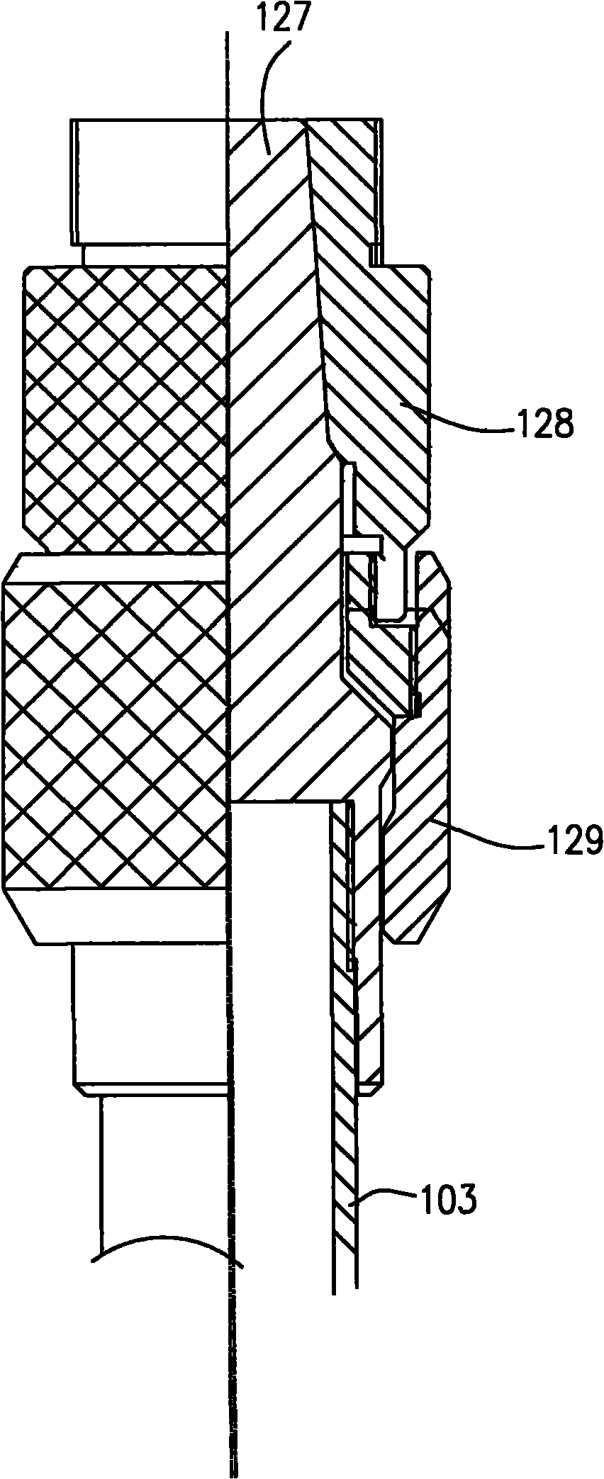
[0037] The telescopic rod 100 of the present invention includes at least two sliding rods, figure 1 The three-section slide bar is taken as an example for illustration, but the present invention is not limited thereto. Such as Figure 1-10 As shown, the telescopic rod 100 includes a first sliding rod 101 at the lower part, a second sliding rod 102 sleeved in the first sliding rod 101 and located in the middle, and a second sliding rod 102 sleeved in the second sliding rod 102 and located at the upper part. Three sliders 103 .

[0038] The bottom of the first slide bar 101 is closed. In the illustrated embodiment, the bottom of the first slide bar 101 is closed by a plunger-shaped slide bar cap 106. The slide bar cap 106 is provided with external threads. The first slide bar 101 Internal threads are provided inside the lower end, and the slide bar cap 106 is fixed to the bottom of the first slide bar 101 through threads. Inside the first slide bar 101 and above the slide bar...


PUM


Abstract

The invention relates to an expansion bar, at least comprising a first slide bar and a second slide bar which are in sliding joint with each other, wherein the second slide bar is positioned on the upper part and is sleeved in the first slide bar. The expansion bar also comprises a nozzle, a clamping claw and a first locknut, wherein the lower part of the nozzle is fixed at the upper end of the first slide bar in a surrounding manner and the upper part thereof is provided with an external thread; the lower part of the clamping claw is arranged in the nozzle, and the upper part of the clamping claw, which is exposed out of the nozzle, is provided with a truncated cone-like peripheral surface and surrounds the second slide bar; and the first locknut is sleeved outside the clamping claw, the lower part of the first locknut is provided with an internal thread meshed with the external thread and the first locknut is provided with a truncated cone-like internal surface which extrudes the truncated cone-like peripheral surface and ensures the clamping claw to clasp the second slide bar. The expansion bar can maintain tight connection even on the oscillatory occasions to prevent rotation. Meanwhile, when accidentally falling down, the second slide bar can be cushioned, thus avoiding impact on the bottom. The lockpin component arranged on the expansion link can avoid detachment among the slide bars.

Description

technical field [0001] The invention relates to a telescopic rod. Background technique [0002] At present, lighting fixtures need to be lifted and lowered in many occasions to meet the needs of on-site lighting. This type of lighting fixture usually adopts a telescopic rod, and the light-emitting component is fixed on one end of the telescopic rod, and the height of the light-emitting component can be changed by adjusting the telescopic state of the telescopic rod. [0003] These telescopic rods have different structures and telescopic methods, and are mainly divided into mechanical telescopic rods, hydraulic telescopic rods, and pneumatic telescopic rods. Among them, the structure of the hydraulic telescopic rod and the pneumatic telescopic rod is relatively simple, but the cost is relatively high. The structure of the mechanical telescopic rod is relatively complicated, but the cost is low. [0004] The mechanical telescopic rods currently used, especially the multi-se...

Claims


Application Information

Patent Timeline
Patent Type & Authority Applications(China)
IPC IPC(8): F21V21/22
Inventor 周明杰欧阳征定
Owner OCEANS KING LIGHTING SCI&TECH CO LTD
Learn More