

Single-piece standoff post base for retrofit
a single-piece, stand-off technology, applied in the direction of mechanical equipment, building repairs, fastening means, etc., can solve the problems of not finding the necessary resistance to uplift, and achieve the effect of less manufacturing cost, less storage cost and minimal cos
- Summary
- Abstract
- Description
- Claims
- Application Information
AI Technical Summary
Benefits of technology
Problems solved by technology
Method used
Image

Examples
Embodiment Construction
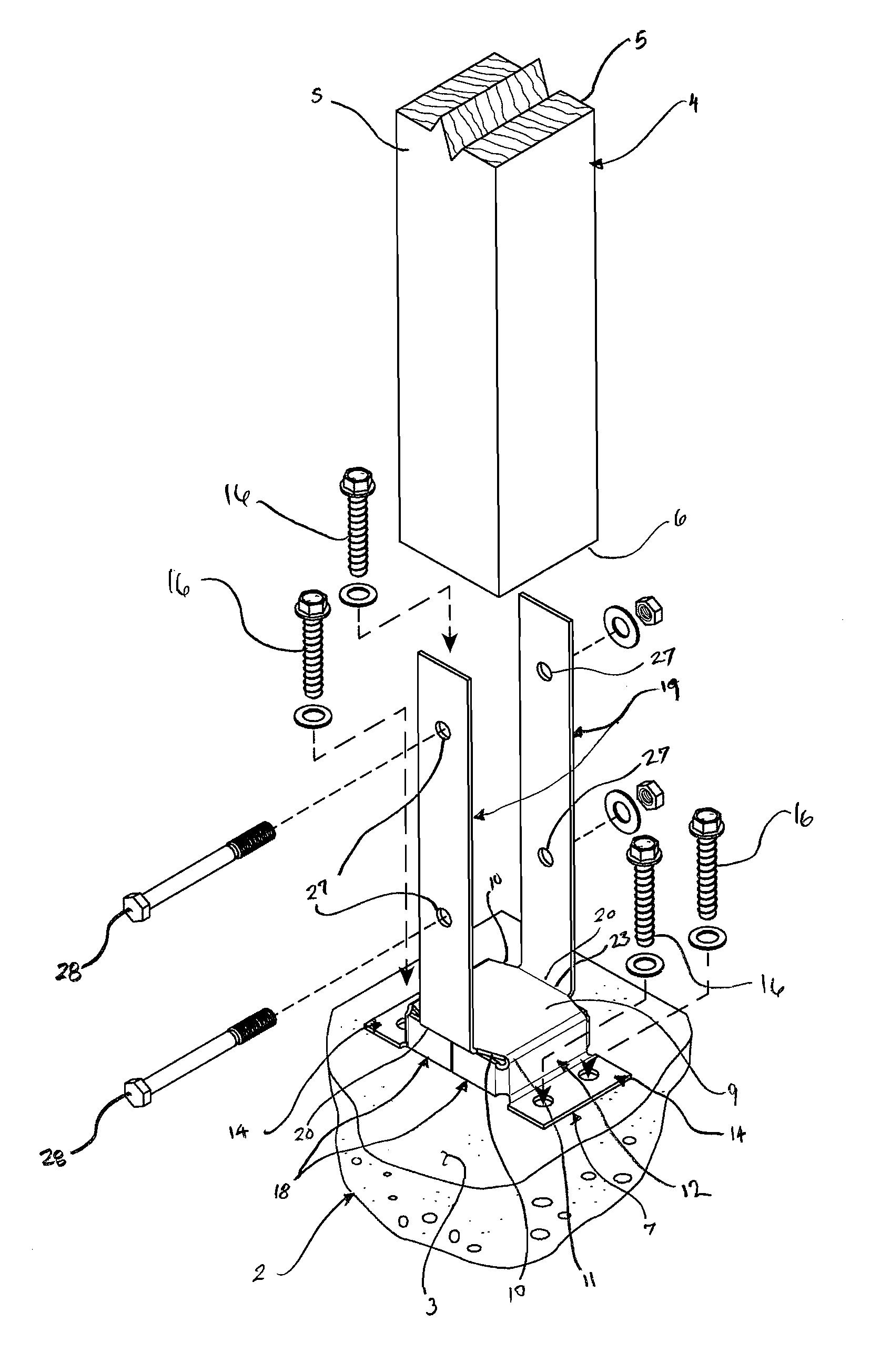
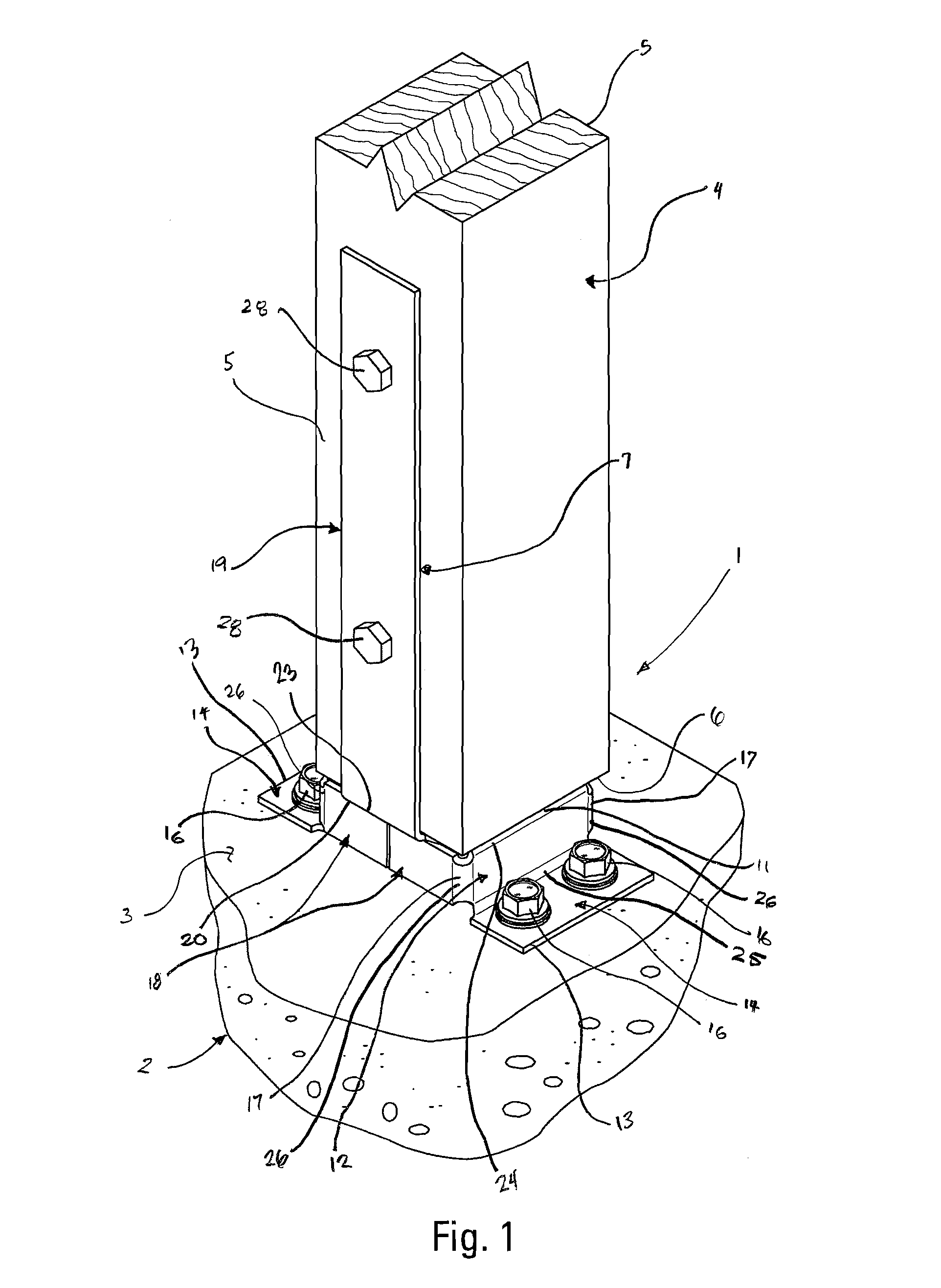
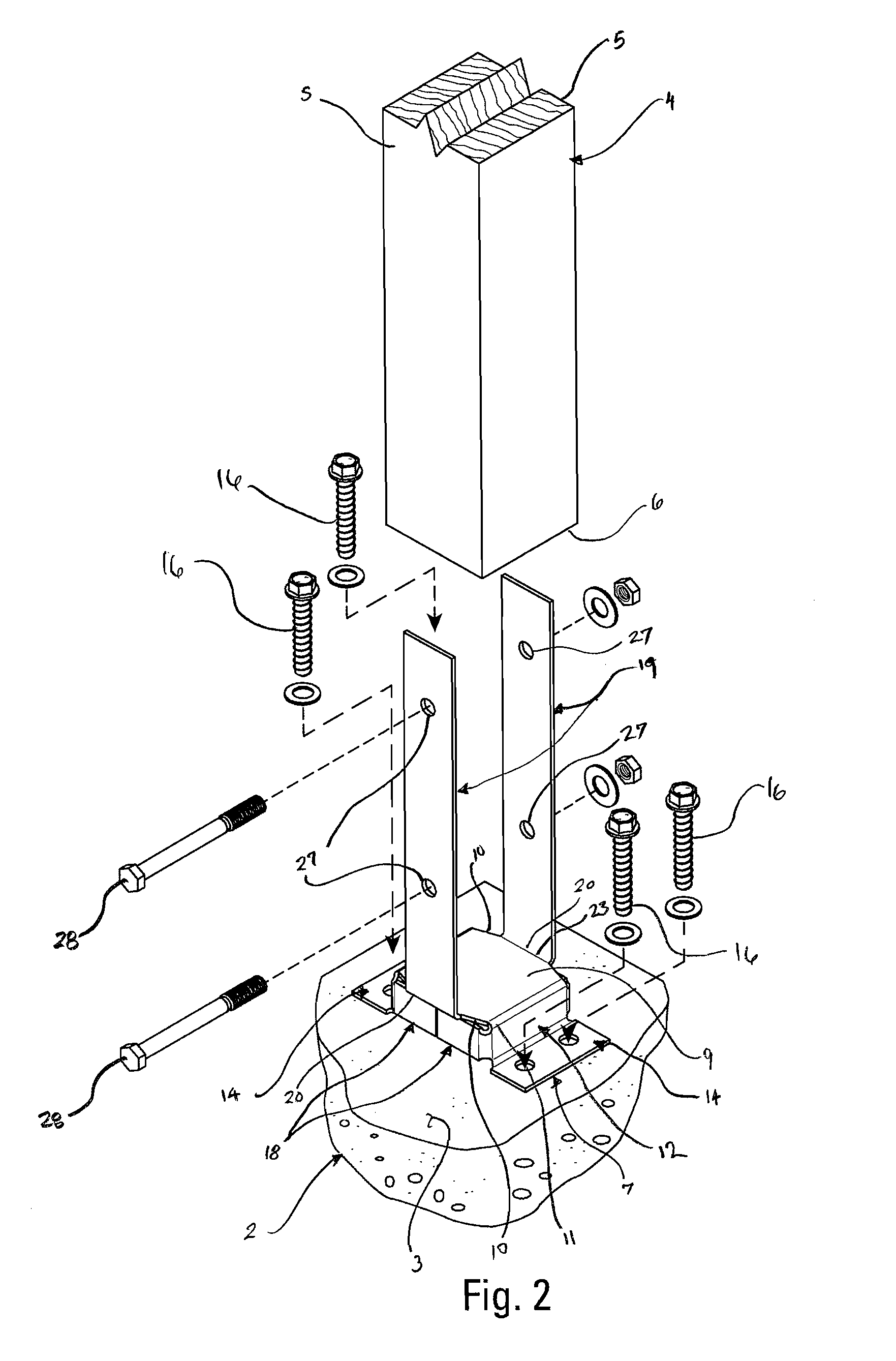
[0018]As shown in FIG. 1, the present invention is a post to foundation connection 1. The connection 1 preferably comprising a concrete foundation 2 with an upper support surface 3, an elongated structural member 4 mounted in an upright orientation above the foundation 2, and a unitary foundation connector 7. Preferably, the elongated structural member 4 as first and second sides 5 that occupy parallel vertical planes and a base 6 that joins the first and second sides 5 at their lowest extremities and that occupies a horizontal plane. The elongated structural member 4 is preferably a post 4. As shown in FIG. 4, the connector 7 is preferably formed from a sheet metal blank 8 of uniform thickness.
[0019]As shown in FIGS. 1-3, preferably the connector 7 has a base member 9 that is disposed in registration with the base 6 of the elongated structural member 4, underneath the elongated structural member 4. The base member 9 preferably has horizontally separated first and second side edges ...
PUM
 Abstract
Description
Claims
Application Information