Method and system for controlling uplink transmitting power of terminal
A technology for transmitting power and controlling terminals, which is applied in the field of communication and can solve problems such as uplink interference
Active Publication Date: 2012-07-18
ZTE CORP
View PDF3 Cites 7 Cited by
- Summary
- Abstract
- Description
- Claims
- Application Information
AI Technical Summary
Problems solved by technology
[0004] The technical problem to be solved by the present invention is to provide a method and system for controlling the u
Method used
View moreImage
Smart ImageViewing Examples
Examples
 PUM
 Abstract
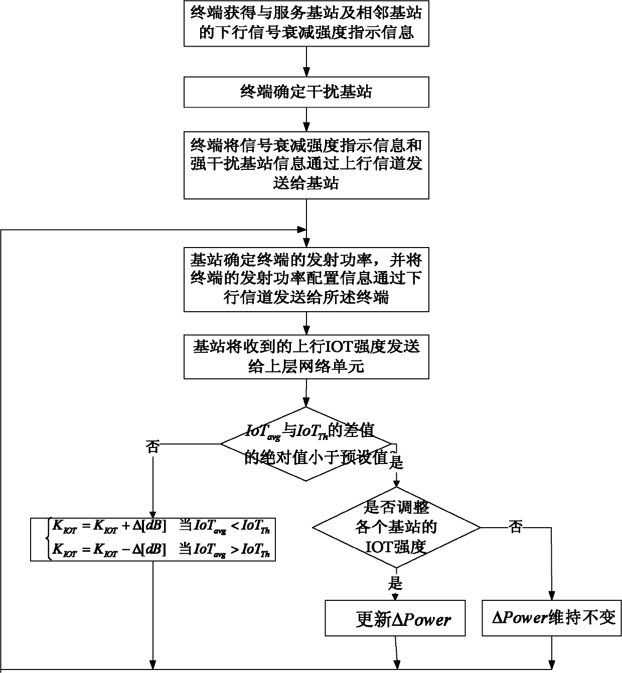
The invention discloses methods and a system for controlling the uplink transmitting power of a terminal. The methods are applied to a system consisting of a plurality of adjacent base stations. One method comprises the steps of: reporting information of all interference base stations which interfere the terminal on uplink data transmission to a service base station; and acquiring a loss value of an uplink propagation path between each interference base station and the terminal by the service base station according to the received information of the all the interference base stations, then, working out the uplink transmitting power of the terminal according to the accumulated loss values of the uplink propagation paths and a preset control factor of interference-to-noise ratio in the local base station, and configuring the terminal with the uplink transmitting power. The other method comprises the steps of: reporting downlink signals between the terminal and the service base station, the interference-to-noise ratio and a propagation path loss value, which are measured by the terminal, to the service base station by the terminal; and by taking the accumulated sum of the received downlink signals, the interference-to-noise ratio and the propagation path loss value as well as the preset control factor of the interference-to-noise ratio in the local base station as the uplink transmitting power of the terminal, configuring the terminal with the uplink transmitting power by the service base station.
Description
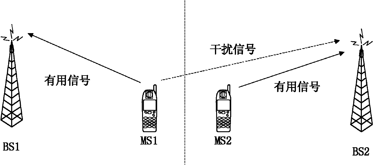
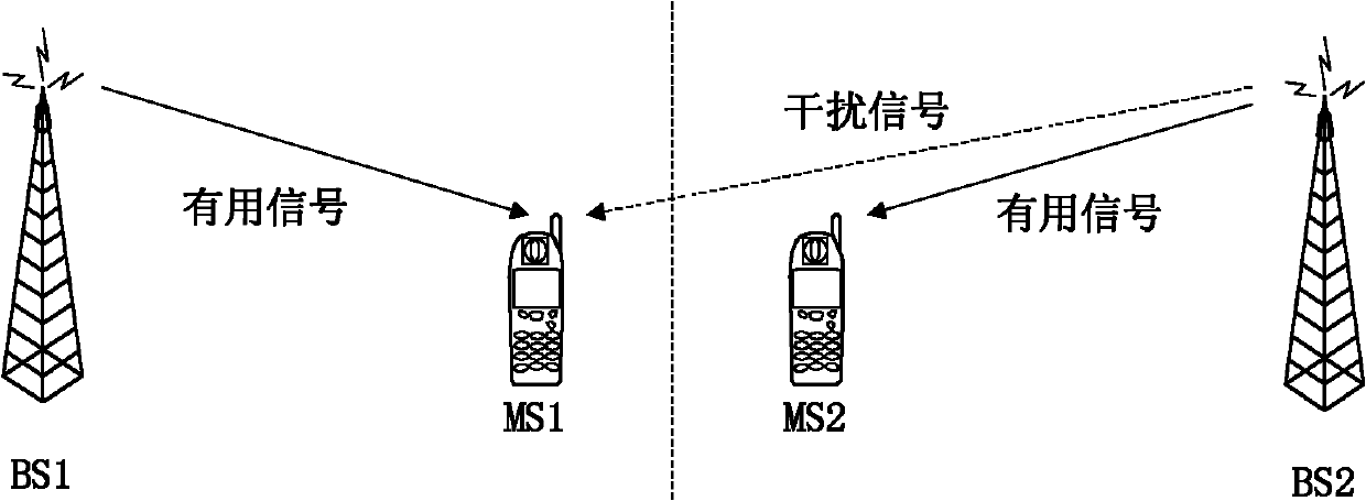
technical field [0001] The present invention relates to the communication field, in particular to a method and system for controlling uplink transmission power of a terminal. Background technique [0002] Inter-cell interference is an inherent problem in cellular mobile communication systems, which seriously affects system capacity. The reason for this is that users using the same frequency resources in each cell will interfere with each other. [0003] Such as figure 1 As shown, BS (Base Station, base station) 1 and BS2 are serving base stations of MS (Mobile Station, terminal) 1 and MS2 respectively, assuming that the set of subcarriers used for uplink transmission allocated by BS1 to MS1 is SC1, and BS2 is allocated to MS2 The set of subcarriers used for uplink transmission is SC2, and the intersection of SC1 and SC2 is SC. If the SC is not an empty set, then when BS2 receives the uplink signal sent by MS2, it will also simultaneously receive the wireless signal sent by...
Claims
Login to View More Application Information
Patent Timeline
 IPC IPC(8): H04W52/14H04W52/24
CPCH04W52/146
Inventor 刘锟鲁照华罗薇李卫敏肖华华
Owner ZTE CORP
Features
- R&D
- Intellectual Property
- Life Sciences
- Materials
- Tech Scout
- Unparalleled Data Quality
- Higher Quality Content
- 60% Fewer Hallucinations
Learn More Browse by: Latest US Patents, China's latest patents, Technical Efficacy Thesaurus, Application Domain, Technology Topic, Popular Technical Reports.
© 2025 PatSnap. All rights reserved.Legal|Privacy policy|Modern Slavery Act Transparency Statement|Sitemap|About US| Contact US: help@patsnap.com


