

Adjustable filter
A filter and adjustment structure technology, applied in the field of communication, can solve the problem of the influence of the tuning screw on the product index, etc., and achieve the effects of large tuning range, low intermodulation reduction, and easy tuning.
- Summary
- Abstract
- Description
- Claims
- Application Information
AI Technical Summary
Problems solved by technology
Method used
Image

Examples
Embodiment 1
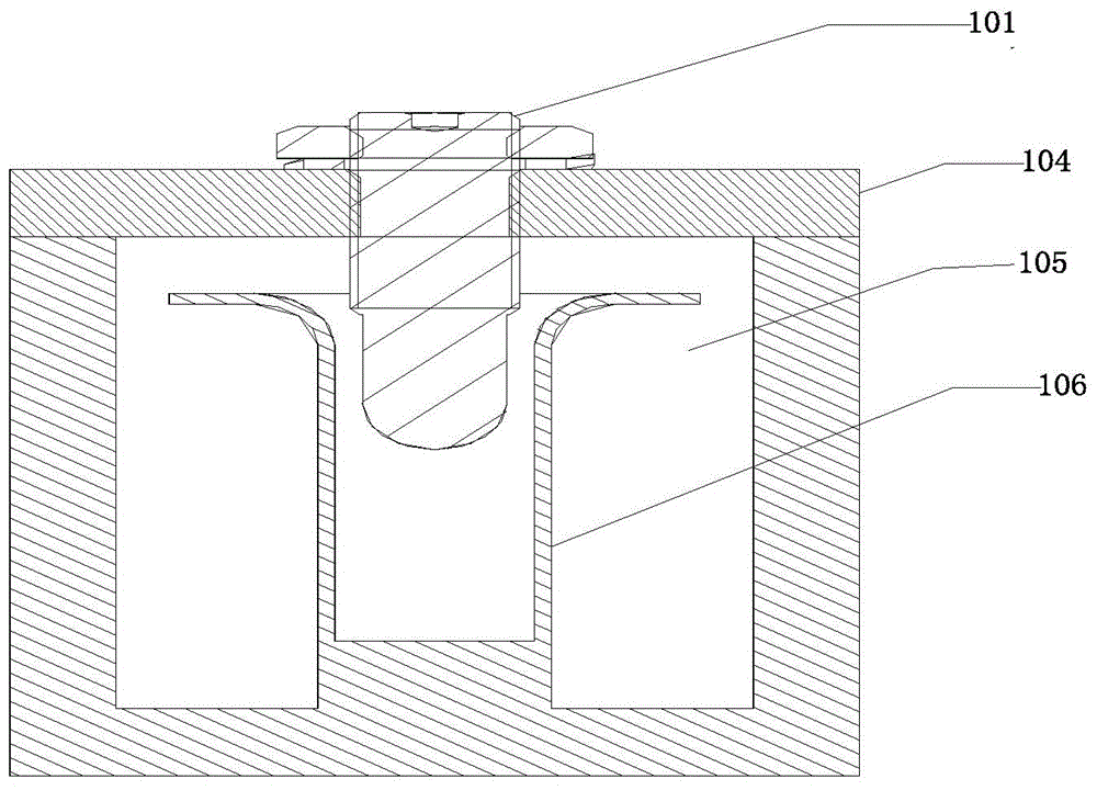
[0032] A tunable filter includes a cavity and a resonant rod arranged in the cavity. The resonant rod includes a movable part and a fixed part. The fixed part is fixed inside the cavity. The movable part is sleeved with the fixed part, and the movable part further includes The adjustment structure passes through the movable part and out of the cavity to adjust the height of the movable part relative to the fixed part.
[0033] In the tunable filter in the embodiment of the present invention, the fixed part of the resonant rod is a metal tube, which can be integrally formed with the filter cavity or assembled in the cavity. The movable part of the resonance rod is also a tube body, and the fixed part of the resonance rod is sleeved on the movable part of the resonance rod. The movable part of the resonance rod is provided with an adjusting structure, which passes through the movable part and out of the cavity, and adjusts the height of the movable part relative to the fixed part o...
Embodiment 2
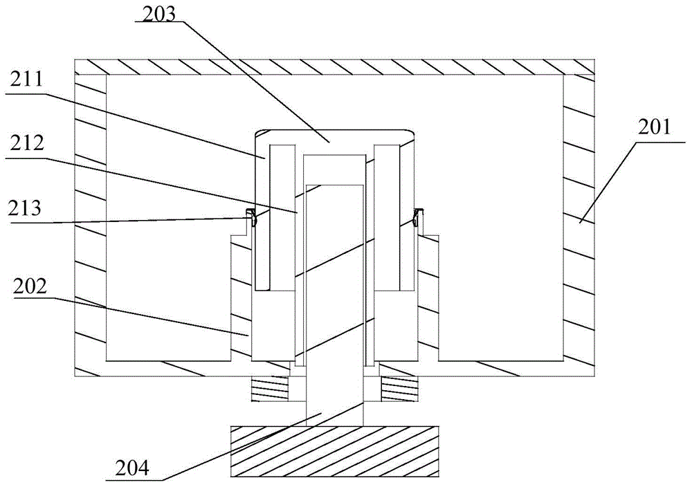
[0044] A tunable filter in this embodiment, such as figure 2 As shown, it includes a cavity 201, a resonance rod arranged in the cavity, the resonance rod includes a movable part 203 and a fixed part 202, the fixed part 202 is fixed inside the cavity, the movable part 203 is sleeved with the fixed part 202, and the movable part 203 also includes an adjusting structure 204 that passes through the movable part 203 and out of the cavity to adjust the height of the movable part 203 relative to the fixed part 202.
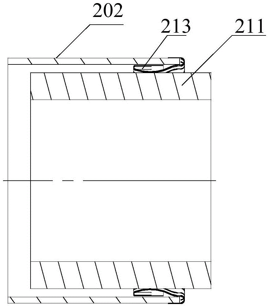
[0045] The movable part 203 of the resonance rod in this embodiment also includes an inner tube 212 of the movable part and an outer tube of the movable part extending radially outward from the top of the inner tube and bending and extending along the axial direction of the inner tube. The inner tube 212 of the movable resonance rod is coaxial with the fixed part 202 and its outer diameter is smaller than the inner diameter of the fixed part 202. The outer tube 211 of the ...
Embodiment 3
[0057] A tunable filter in this embodiment, such as Image 6 As shown, it includes a cavity 401, a resonance rod arranged in the cavity, the resonance rod includes a movable part 403 and a fixed part 402, the fixed part 402 is fixed inside the cavity, the movable part 403 is sleeved with the fixed part 402, and the movable part 403 also includes an adjusting structure 404, which passes through the movable part 403 and out of the cavity to adjust the height of the movable part 403 relative to the fixed part 402.
[0058] The movable part 403 of the resonance rod in this embodiment also includes a movable part inner tube 412 and a movable part outer tube that extends radially outward from the top of the inner tube and is bent and extended in the axial direction of the inner tube. The inner tube 412 of the movable resonance rod is coaxial with the fixed part 402 and its outer diameter is smaller than the inner diameter of the fixed part 402. The outer tube 411 of the movable part is ...
PUM
 Abstract
Description
Claims
Application Information